TM 9-2320-211-20
d. Installation.
(1) Make sure the element is free to move in
the bore and does not hang up.
( 2 ) Install a new preformed packing and
cover plate, making sure that the indicator spiral
blade enters the slot in the element cover.
NOTE
The cover plate can be installed in any of
four positions.
(3) Install the cover plate so the indicator can
easily be read.
2-297. Floodlight Lamp Unit
Refer to paragraph 2-281.
2-298. Floodlight Switch
Refer to paragraph 2-282.
2-299. Floodlight
Refer to paragraph 2-283.
2-300. Floodlight Cables
Refer to paragraph 2-284.
2-301. Electric Brake Lock
Governor
override
solenoid
replacement.
Refer to paragraph 2-285.
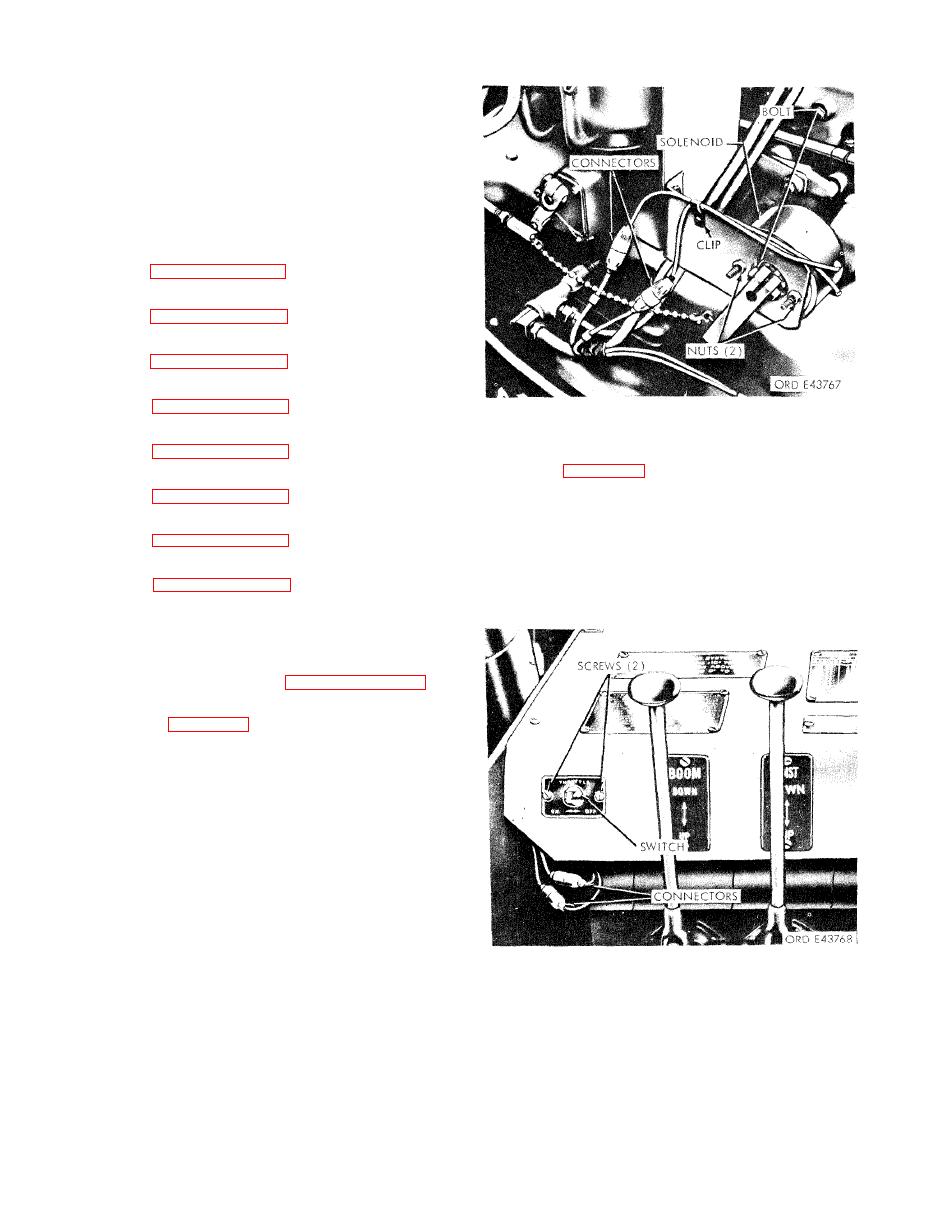
2-302. Warning Light Switch.
a. Removal.
Refer to paragraph 2-287.
(1) Disconnect the two electrical leads from
2-303. Floodlight Switch (Inside Cab)
the override switch at the connectors as shown.
Refer to paragraph 2-288.
(2) Remove the two screws securing the
override switch to the panel. Remove the switch.
2-304. Control Lever Knob
Refer to paragraph 2-289.
2-305. Restrictor Valve
The restrictor valve, located in the oil motor and
ram cylincler hydraulic lines, will be inspected
during the removal and installation of the hydraulic
lines and fittings. Refer to paragraph 2-280.
2-306. Governor Override Solenoid
a. Removal.
(1) Disconnect the solenoid electrical leads at
the connectors as shown.
(2) Remove the screw from the clip securing
the electrical leads to the bracket.
(3) Remove the two nuts securing the solenoid
to the bracket, and remove the solenoid.
b. Installation.
(1) Secure the solenoid to the bracket with the
two nuts.
(2) Position and secure the electrical leads
with the clip and screw.
(3) Connect the solenoid electrical leads at the
connectors.


