
TM 9-2320-211-20
(e) If the idle mixture adjustment results i n
an increase in idling speed great enough to require
re-setting the throttle adjusting screw, the idle
adjusting screws must be re-set.
b. Removal.
(1) Loosen the hose clamp (14, fig, 2-43)
securing the air cleaner-to-carburetor inlet hose
(10) to the air inlet sleeve on the carburetor, and
remove the hose from the sleeve.
(2) Remove the nut from the ball stud at the
back side of the throttle valve plate lever (15) and
remove the throttle cross-shaft-to-carburetor rod
lever. Replace the nut on the ball stud to prevent its
loss.
(3) Unscrew the connector securing the fuel
pump-to-carburetor line (16) to the elbow at the
front of the carburetor, and remove the line.
c. Installation.
(4) U n s c r e w t h e c o n n e c t o r s e c u r i n g t h e
NOTE
governor valve-to-governor line
(17)
to
the
When installing a new or rebuilt carburetor
governor air inlet at the left side of the carburetor,
on the M62, M246, or M543, coordinate
a n d remove the line (all models except M62,
the operation with supporting maintenance
M246, and M543).
personnel.
( 5 ) Unscrew t h e c o n n e c t o r s e c u r i n g t h e
( 1 ) Install a new carburetor carburetor-to-
governor valve control valve-to-governor line (14,
manifold gasket on tbe carburetor mounting studs.
(2) Position the carburetor on the mounting
the carburetor, and remove the line (M62, M246,
studs on the top of the intake manifold, (20) install
and M543).
six safety nuts (19) on the studs, and tighten, the
(6) Unscrew the connector securing the
nuts to 25-30 ft.-lb. torque.
carburetor-to-governor valve line (18 fig. 2-43) to
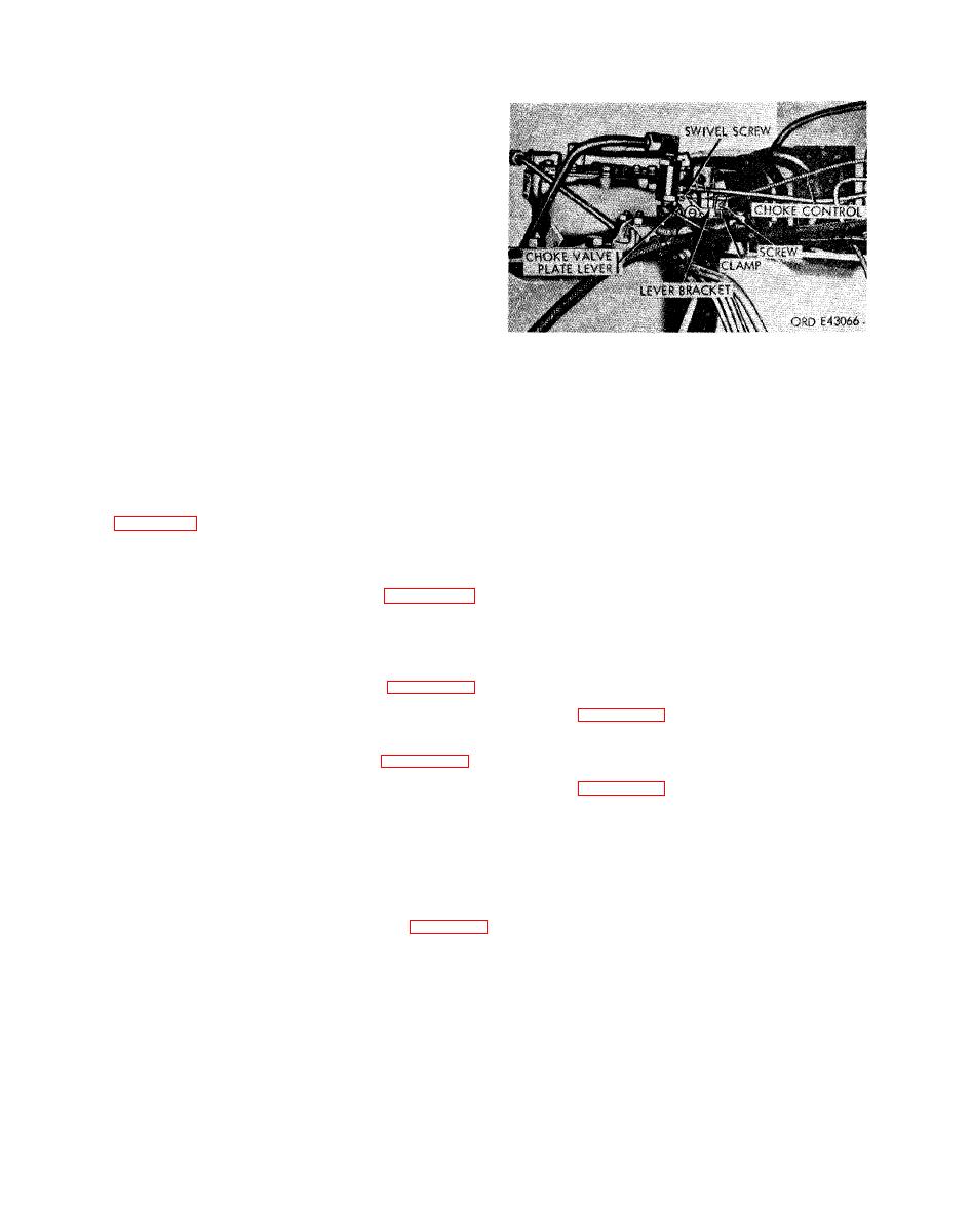
(3) Insert the choke control wire in the hole in
the elbow at the right rear of the carburetor, and
the end of the choke lever swivel; but do not tighten
remove the line (all models except M62, M246,
the swivel screw. Position the choke control (fig. 2-
a n d M543).
6 6 ) under the choke lever bracket clamp and
( 7 ) Unscrew t h e c o n n e c t o r s e c u r i n g t h e
tighten the clamp screw.
carburetor-to-governor valve line (12, fig. 2-44) to
(4) Position the carburetor-to-governor valve
the tee at the right of the carburetor, and remove
line (18, fig. 2-43) at the elbow on the right rear of
t h e line (M62, M246, and M543).
the carburetor, a n d tighten the connector (all
(8) Unscrew t h e c o n n e c t o r s e c u r i n g the
m o d e l s except M62, M246, and M543).
carburetor-to-governor valve line (13, fig. 2-44) tee
(5) Position the carburetor-to-governor valve
at the right rear of the carburetor, and remove the
line (12, fig. 2-44) at the tee at the right rear of the
l i n e (M62, M246, and M543 only).
carburetor, a n d tighten t h e c o n n e c t o r ( M 6 2 ,
(9) Loosen the choke lever swivel screw (fig.
M 2 4 6 , and M543 only).
2-66) securing the choke control wire to the choke
(6) Position the carburetor-to-governor valve
valve plate lever at the left side of the carburetor.
line (13) at the tee at the right rear of the car-
Loosen the choke lever bracket clamp screw, and
buretor, and tighten the connector (M62, M246,
r e m o v e the choke control from the lever and
a n d M543 only).
bracket.
(7) Position the governor valve control valve-
(10) Remove the six safety nuts (19, fig. 2-43)
to-governor line (14) at the governor air inlet on the
from the carburetor mounting studs at the car-
left side of the carburetor, and tighten the con-
buretor base, and remove the carburetor from the
n e c t o r (M62, M246, and M543 only).
i n t a k e manifold (20). Remove and discard the
(8) Position the governor valve-to-governor
carburetor-to-manifold gasket.
