
TM 9-2320-211-20
quickly, observing the minimum and maximum
NOTE
gage readings.
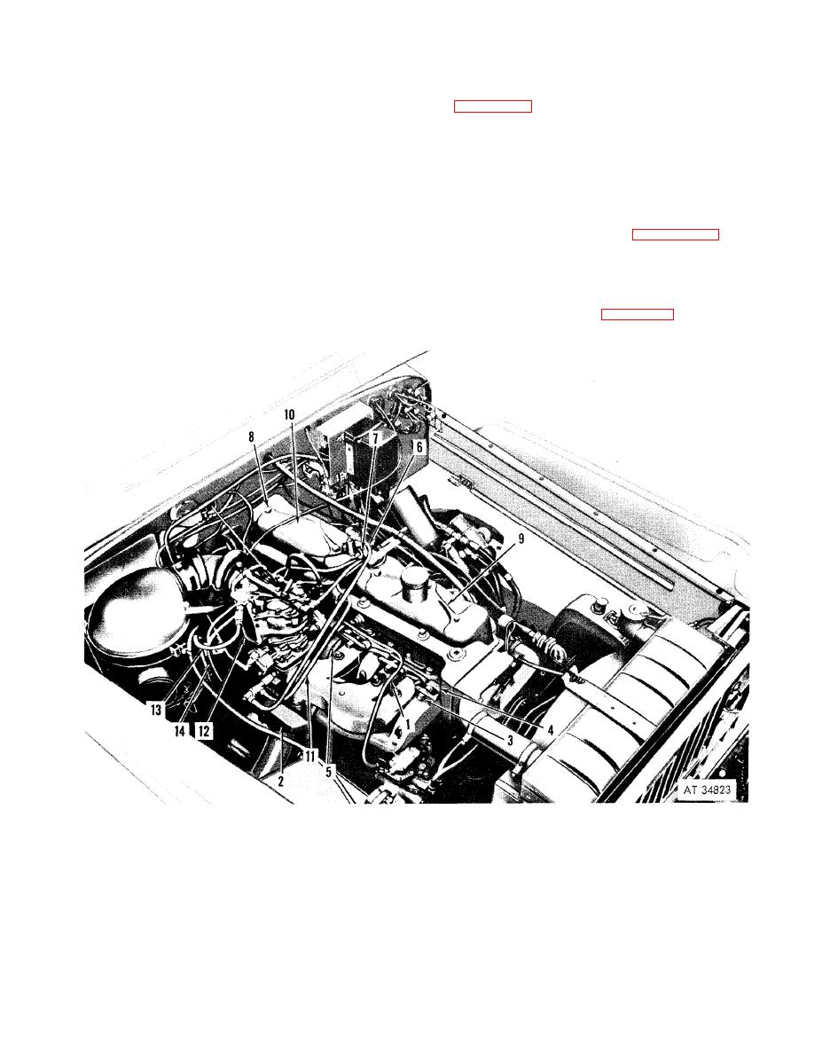
The key numbers in parentheses are for
(5) Failure of the manifold vacuum to drop to
approximately two inches and to rise to at least 24
(1) Disconnect the vacuum line (2) and
inches, as engine speed decreases and increases,
distributor ventilation line (3) at the intake
indicates diluted engine oil, faulty piston rings, or
manifold.
(2)
Disconnect
the
crankcase
ventilation
abnormal restriction of the carburetor, air cleaner,
or exhaust system.
shutoff valve control (4) on those vehicles equipped
NOTE
with a manually controlled crankcase ventilation
The vacuum gage readings in (2) above
system.
apply to sea level. These readings will be
(3) Remove the carburetor (para 2-65).
reduced by approximately one inch of
(4) On vehicles equipped with a primer pump
m e r c u r y for each 1,000 feet of altitude
unscrew the connector at the priming tee (5), and
above sea level.
disconnect the tube from tee.
( 6 ) Stop the engine. R e m o v e the vacuum
( 5 ) Disconnect both ends of the air com-
gage. Install and tighten the plug (1) in the hole.
presser-to-governor line (1, fig. 2-44).
b. Removal.
8
Cap screw
2 Exhaust pipe mounting flange
9
Front rocker arm cover
3 Hexagon nut
10
Rear rocker arm cover
4 Manifold clamp
11
Distributor vent line
5 Heat shield
12
Carburetor-to-governor valve line
6 Vacuum line
13
Carburetor-to-governor valve line
7 Crankcase ventilating line connector
14
Governor valve control valve-to-governor line
