
TM 9-2320-366-20-4
This task covers:
a. Removal
c. Follow-On Maintenance
b. Installation
INITIAL SETUP
Equipment Conditions
Tools and Special Tools (Cont)
Engine shut down (TM 9-2320-366-10-1).
Goggles, Industrial (Item 15, Appendix C)
Cab raised (TM 9-2320-366-10-1).
Wrench Set, Socket, (Item 50, Appendix C)
Tools and Special Tools
Materials/Parts
Tool Kit, Genl Mech (Item 46, Appendix C)
Nut, Self-Locking (Item 161, Appendix G)
Wrench, Torque, 0-600 lb-ft (Item 60, Appendix C)
Nut, Self-Locking (Item 162, Appendix G)
WARNING
Wear appropriate eye protection when
working under vehicle due to the possibility
of falling debris. Failure to comply may
result in injury to personnel.
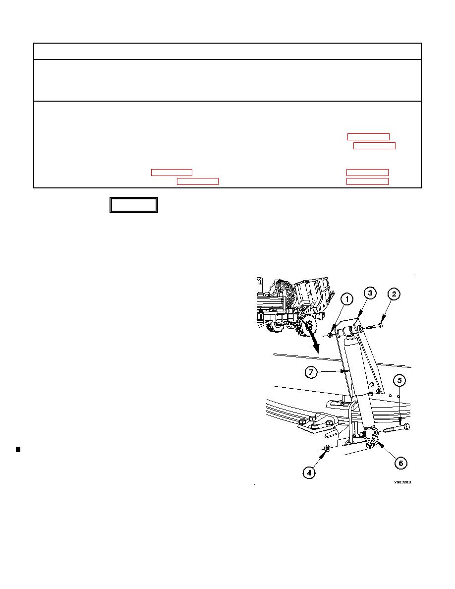
a. Removal.
(1) Remove self-locking nut (1) and screw (2) from upper
bracket (3). Discard self-locking nut.
(2) Remove self-locking nut (4) and screw (5) from lower
bracket (6). Discard self-locking nut.
(3) Remove shock absorber (7) from upper bracket (3) and
lower bracket (6).
b. Installation.
(1) Position shock absorber (7) in upper bracket (3) with
screw (2) and self-locking nut (1).
(2) Extend or compress shock absorber (7) length to align
with holes in lower bracket (6).
(3) Position shock absorber (7) in lower bracket (6) with
screw (5) and self-locking nut (4).
(4) Tighten self-locking nut (1) to 200-236 lb-ft (271-320
Nm).
(5) Tighten screw (5) to 296-370 lb-ft (401-502 Nm).
Change 1
