C3, TM 9-2320-211-20
(5) Position the metal shield at the bottom of the air
hydraulic cylinder mounting brackets (fig. 2-184), install
a. Removal.
four bolts and nuts, and tighten the nuts.
(1) Remove the wheel and tire assembly (para 2-
(6) Bleed the air hydraulic cylinder and wheel
207).
cylinders (para 2-190a).
210).
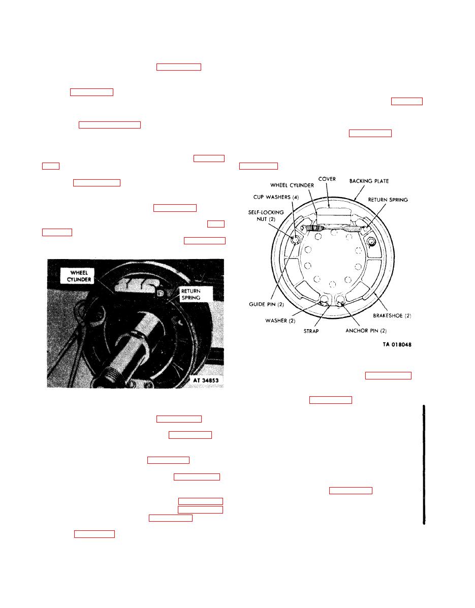
2-192. Brake Wheel Cylinders.
a. Maintenance. Bleed each wheel cylinder as
(3) Install the clamp over the ends of the wheel
cylinder to hold the wheel cylinder pistons in position.
described in paragraph 2-190a.
b. Removal.
brakeshoes.
(1) Remove the wheel and tire assembly (para 2-
(5) Remove two retaining nuts, four cup washers,
207).
and two outer springs securing brakeshoes to guide pins
(3) Unscrew the connector securing the hydraulic
brake line (fig. 2-178) to the wheel cylinder at the back
side of the backing plate assembly and remove the line
from the cylinder.
of the brakeshoes.
plate assembly, and remove the wheel cylinder (fig. 2-185)
with its cover from the front side of the backing plate.
anchor pins assembly.
anchor pins from the front side of the backing plate
(7) Pull the anchor pins from tbe bore at the lower
end of the brakeshoes (fig. 2-186).
(8) Remove the two cup washers, two innersprings,
c. Installation.
guide pin retaining star washer and nut. Drive out old
guide pins.
cover on the front side of the backing plate assembly,
b. Installation.
install the two wheel cylinder capscrews (fig. 2-178) with
(1) Install large end of redesigned guide pin into its
lockwashers in the holes at the back side of the backing
hole in backing plate and fasten with star washer and
plate, and tighten the capscrews.
locknut.
(2) Hold pin with a 3/8 inch open end wrench and
brakeshoes.
tighten nut until shoulder of pin bottoms against the
backing plate.
the wheel cylinder inlet on the rear backing plate
assembly and tighten the connector.
pin plate in the bore at the lower end of the brakeshoes.
Turn the anchor pins to position the punchmarks (which
indicate the high side of the anchor pin cams) toward
each other.
(7) Adjust the brakes, using the minor adjustment
procedures (para 2-188a(2)).


