
TM 9-2320-211-20
for evidence of holes, tears, or seal damage. If the
element is serviceable return it to stock.
NOTE
The air restriction indicator will show some
red when the element is partially restricted
as an advance indication of the need for
servicing. W h e n an extended period of
o p e r a t i o n is planned and the indicator
shows a state of dust plugging (partial red
i n d i c a t i o n ) too great for mission com-
pletion, the air cleaner must be serviced.
(3) I n s t a l l a t i o n .
(a) Install the element into the air cleaner
housing.
(b) Press the locking mechanism into the
air cleaner housing, and turn it clockwise until it is
locked in the clamps.
(c) Install the cover onto the air cleaner
housing lock latches.
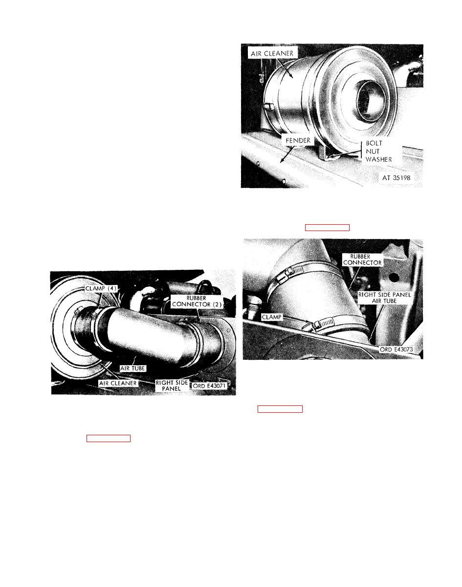
b. Removal.
(3) Loosen the clamp securing the rubber
(1) Loosen the two clamps securing the two
connector to the air tube, Separate the connector
from the air tube (fig. 2-77).
rubber connectors and the air tube assembly (fig. 2-
75). Remove the connectors and tube assembly
f r o m the vehicle. If necessary, loosen the two
clamps to separate the air tube from the connectors.
(4) Disconnect the ventilation line from the air
tube, and remove the three nuts and bolts securing
the air tube to the right side panel. Remove the air
tube (fig. 2-78).
(2) Remove the six nuts, bolts, and washers
securing the air cleaner. Lift the air cleaner off of
the fender (fig. 2-76).
