
TM 9-2320-211-20
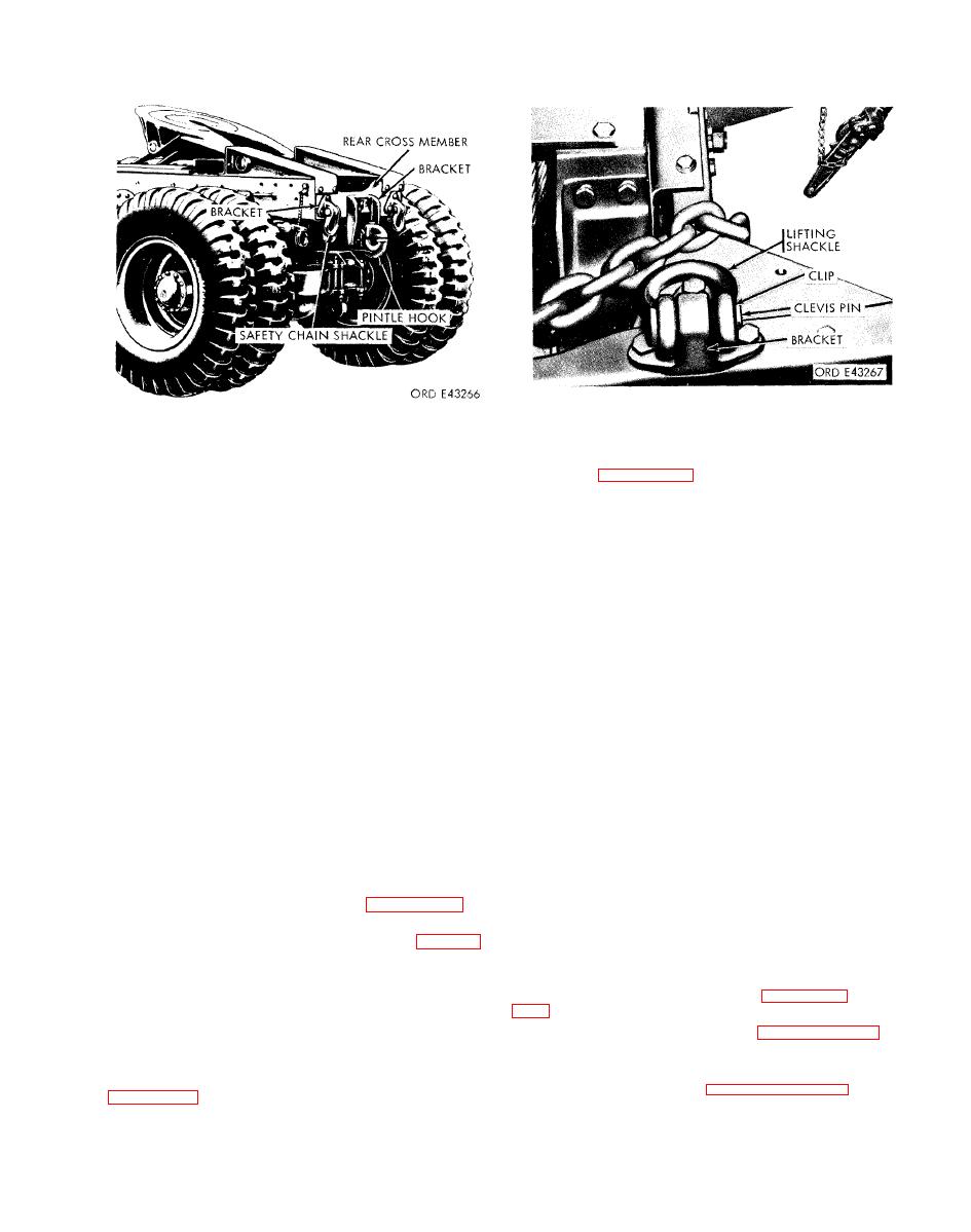
(2) Installation. Position the shackle to the
mounted to rear of vehicle.
bracket. Insert the clevis pin through the shackle
and bracket (fig. 2-212). Secure the pin with the
(3) R e p a i r .
clip.
(a) Clean the hook in a drycleaning solvent
b. Bracket.
or mineral spirits paint thinner. If necessary, use a
(1) R e m o v a l .
stiff-bristle brush to clean off the dirt that still
(a) Remove the lifting shackle as described
clings to the hook.
in a(1) above.
(b) Inspect the hook shaft and the threaded
(b) Remove the two capscrews and safety
end of the shaft for signs of excessive wear and / or
nuts securing the front end of the bracket to the top
damage. Also inspect the hook, lock, and latch for
of the front bumper.
damage. Check the lubrication fittings.
(c) Remove the safety nut, short spacer,
(c) Use a fine stone, if necessary, to remove
cap screw, and long spacer securing the rear end of
any raised metal or scores; replace the latch chain
the bracket to the top of the front bumper. Remove
if it is missing, broken, or damaged in any way.
the bracket from the bumper.
(4) Installation. Insert the threaded end of the
(2) Installation.
hook in the hole in the mounting bracket (fig. 2-
(a) Position the lifting shackle bracket on
212). Secure the hook to the bracket with a plain
top of the front bumper. Secure the front end of the
washer, slotted nut, and cotter pin. Adjust the
shackle to the bumper with two capscrews and
pintle hook to 0.003 / 0.017 inch between the plain
safety nuts.
washer and the mounting bracket, to permit free
(b) Position the long spacer between the
rotation of the pintle.
bumper flanges under the bracket rear mounting
b.
Bracket.
hole. Insert the capscrew through the hole and
(1) Removal. Remove the hook as described
spacer. Install the short spacer and safety nut on
in a(2) above. Unscrew the eight nuts, and remove
the capscrew a t the underside of the bottom
the eight screws securing the bracket to the rear
bumper flange, and tighten the nut.
crossmember. Remove the bracket (fig. 2-211).
(c) Install the lifting shackle as described in
(2) Installation. Secure the bracket to the rear
a(2) above.
crossmember with eight screws and nuts (fig. 2-
211). Tighten the nuts. Install the hook as
a. S h a c k l e .
d e s c r i b e d in a(4) above. L u b r i c a t e the pintle
2-
assembly in accordance with LO 9-2320-211-12.
(1) R e m o v a l . R e f e r
to
a. S h a c k l e .
225a (2), and follow similar procedures.
Remove the clip securing the
(1) Removal.
b. B r a c k e t .
clevis pin. Pull the pin out, and remove the shackle
a n d f o l l o w similar procedures t o r e m o v e t h e
