TM 9-2320-211-20
b. Installation.
(1) Secure the starter to the flywheel with the
three screws.
(2) Connect the three cables to the starter and
starter solenoid with lockwashers and nuts.
2-129. Solenoid
a. Removal.
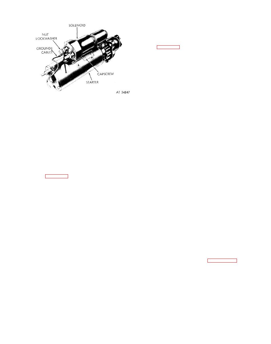
(1) Remove the two nuts and lockwashers
securing t h e g r o u n d c o n n e c t i o n between the
solenoid and starter. Remove the ground cable.
( 2 ) Remove the four screws securing the
solenoid mounting bracket to the starter housing.
Remove the solenoid from the starter.
b. Installation.
(1) Secure the solenoid and its bracket to the
starter with four screws.
(2) Connect the ground cable to the starter
models.
ground terminal and the solenoid terminal with two
lockwashers and nuts.
(2) Remove the three screws s e c u r i n g
the
starter to the flywheel housing. Remove the starter.
Section XX. GENERATING SYSTEM
2-130. General
(c) R e m o v e a n d l i f t t h e k e y f r o m t h e
keyway on shaft.
The generating system consists of the generator, the
b. Installation.
generator regulator, a n d the battery-generator
(1) Generator pulley.
indicator.
(a) Position the key in the keyway on the
2-131. Generator and Generator Pulley
shaft.
(b) Aline the pulley keyway with the key,
a. Removal.
and slip the pulley over the shaft and key.
(1) G e n e r a t o r .
(c) Tap the pulley into position, and secure
(a) R e m o v e t h e c o n n e c t o r n u t o n t h e
it with the self-locking nut and washer.
generator-to-regulator harness at the generator
(2) G e n e r a t o r .
output elbow, and slide the nut back on the har-
(a) Mount the generator on the mounting
ness.
brackets and install the bolt, two spacers, and the
(b) Carefully remove the cables from the
self-locking nut in the mounting hole at each end of
generator, and remove the gasket.
the generator.
(c) Loosen the two generator mounting
NOTE
bolts and nuts.
Do not tighten nuts.
(d) Remove the generator adjusting arm
(b) P o s i t i o n t h e d r i v e b e l t s o v e r t h e
screw, and pivot the generator toward the engine as
generator pulley.
far as possible.
(c) I n s t a l l t h e g e n e r a t o r a d j u s t i n g a r m o n
(e) R e m o v e t h e d r i v e b e l t s f r o m t h e
the generator, and secure it with the adjusting
generator pulley.
screw and lockwasher.
(f) Remove the generator mounting nuts,
lockwashers, and bolts, and lift the generator from
112).
the engine.
(e) Tighten the mounting nuts and bolts.
(2) Generator pulley.
(f) Polarize the generato if a new or rebuilt
(a) Remove the self-locking nut and washer
generator is being installed (c below).
from the tapered drive shaft.
(g) I n s t a l l a g a s k e t a n d c o n n e c t t h e
(b) install a standard 3-legged puller over
generator-to-generator h a r n e s s to the generator
the pulley body. Tighten the puller to the sh:ift end,
output elbow. Tighten the connector nut.
and rap the puller sharply to disengage the pulley
from the shaft.


