
TM 9-2320-366-20-4
NOTE
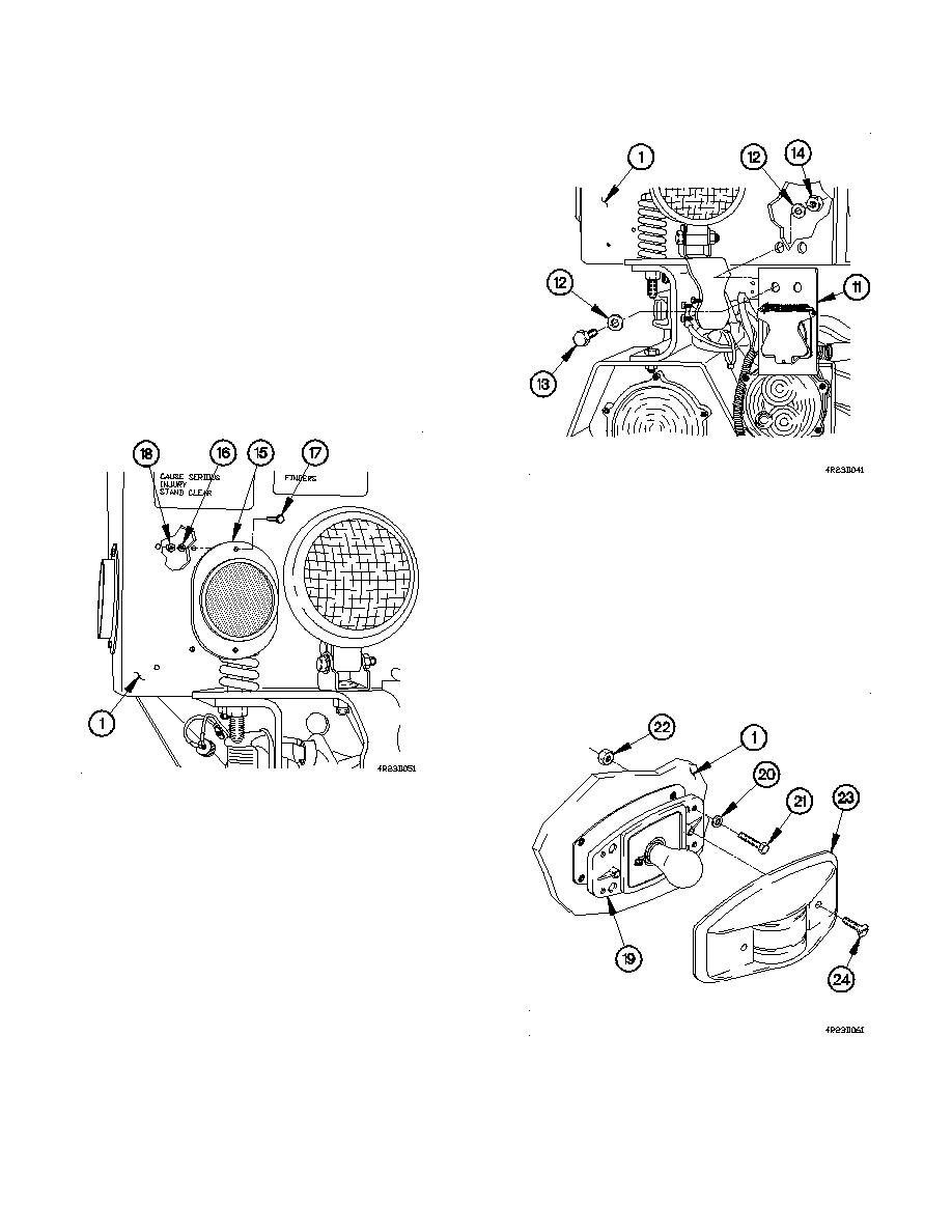
Left and right electrical connector brackets are
installed the same way. Left side shown.
Step (6) and (7) requires the aid of an assistant.
(6) Position electrical connector brackets (11) on tool box (1)
with four washers (12), two screws (13), and self-locking
nuts (14).
(7) Tighten two self-locking nuts (14) to 8-10 lb-ft (11-13
Nm).
(8) Perform steps (6) and (7) on right side electrical
connector bracket.
NOTE
All four reflectors are installed the same way.
One shown.
(9) Install reflector (15) on tool box (1) with two lockwashers
(16), screws (17), and self-locking nuts (18).
(10) Perform step (9) on remaining reflectors.
NOTE
All five clearance lights are installed the
same way. One shown.
(11) Install clearance light (19) on tool box (1) with four
lockwashers (20), screws (21), and self-locking nuts (22).
(12) Install cover (23) in tool box (1) with two screws (24).
(13) Perform steps (11) and (12) on remaining clearance
lights.
16-179
