TM 9-2320-366-20-4
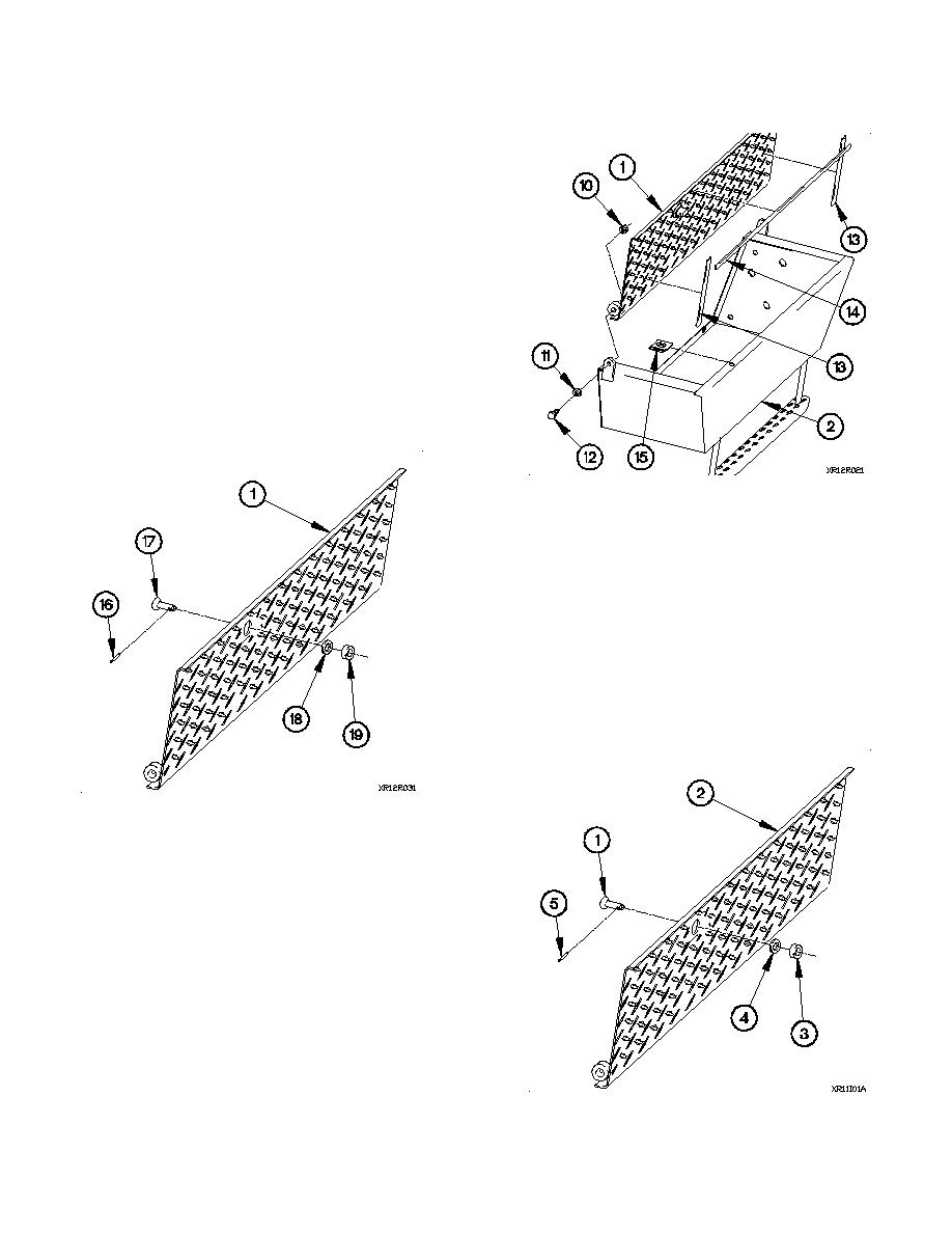
(4) Remove two self-locking nuts (10), washers (11), screws
(12), and cab step tread (1) from cab step (2). Discard
self-locking nuts.
(5) Remove two seals (13) and seal (14) from cab step
tread (1). Discard seals.
(6) Remove turnlock receptacle (15) from cab step (2).
Discard turnlock receptacle.
(7) Remove pin (16) from stud fastener (17).
(8) Remove stud fastener (17), washer (18), and grommet
(19) from cab step tread (1). Discard grommet.
b. Installation.
NOTE
Left and right cab steps are installed the
same way. Left cab step shown.
(1) Position stud fastener (1) in cab step tread (2) with
grommet (3) and washer (4).
(2) Install pin (5) in stud fastener (1).
16-119


