TM 9-2320-211-20
(c) Tape the elbow and tee intake manifold
Remove the tape from the elbow and tee
(a)
openings to prevent excessive air leakage which would
openings of the intake manifold.
cause improper engine idle.
(b) Connect the distributor ventilation line (11,
c. Valve Clearance Adjustment.
fig. 2-44) to the tee.
(1) Start the engine and check the temperature gage
(c) Connect the vacuum line to the elbow.
to be sure that the engine coolant is still at normal
operating temperature.
crankcase ventilating shutoff valve (4, fig. 2-43).
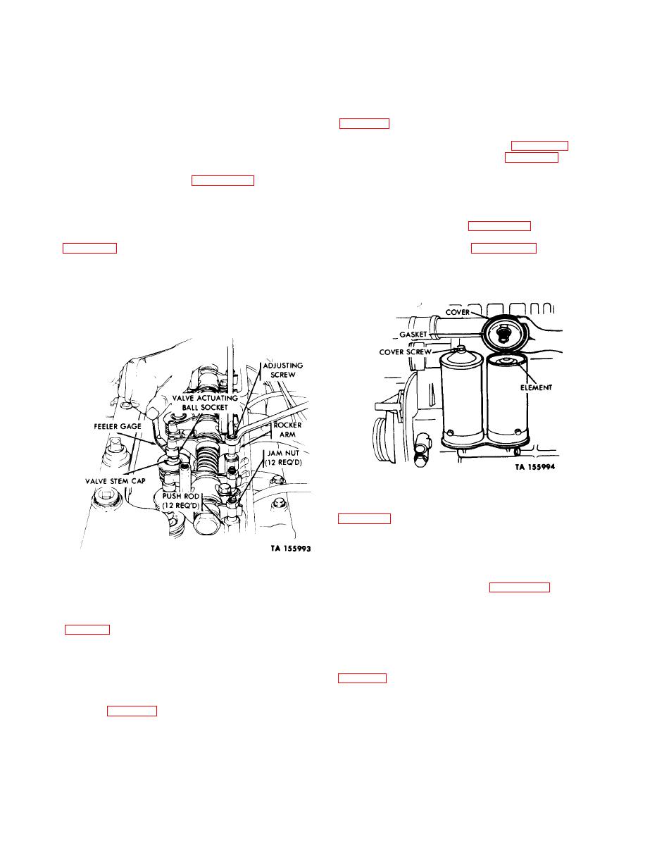
(2) With the engine idling, insert the feeler gage
(7) Start the engine, and check the cylinder head
between the valve stem cap (fig. 2-45) and the valve
cover area for oil leaks.
2-46. Oil Filters.
actuating ball socket at each valve to check for proper
a. Filter Elements.
clearance. Clearance should be .018 inches for intake and
(1) Removal.
.024 for exhaust.
(3) If the clearance is incorrect, using a wrench and
screwdriver, loosen the valve-adjusting screw jamnut
drain into a suitable container.
covers to the filter housings. Remove the covers and
decrease, counterclockwise to increase) until proper
springs.
clearance is obtained.
(4) Hold the screw in the adjusting position, tighten
the jamnut, and again check the clearance.
(5) Repeat (2), (3), and (4) above until all valves are
adjusted to the recommended clearance.
(6) Stop the engine.
(c) Pull the elements out of the housings
(2) Installation.
(a) Use a drycleaning solvent or spirits paint
thinner to clean out the inside of the filter housings and
covers.
(b) Install the drain plugs.
d. Valve Rocker Cover Installation.
filter housings.
(1) Position a new cover gasket and secure the
(d) Add oil to the filters and the engine (LO 9-
cover to the cylinder head with three capscrews (8,
2320-211-12).
fig. 2-44 and washers.
(e) Position the filter cover springs on top of the
(2) If both covers were removed, repeat step (1)
elements.
above to install the other cover.
(f) Position the filter covers with new gaskets on
top of the housings, and secure the covers with nuts
connector gaskets, and secure the connector to the studs
with four lockwashers and nuts. Tighten the nuts.
(g) Run the engine until operating temperature is
reached, and check the filters for leaks.
valve (4, fig. 2-43), push the fording valve control handle
b. Filter Housings.
in.
(1) Removal.
(5) If the engine has no ventilating shutoff valve,
(a) Follow the procedures described in a(1) above
proceed as indicated in steps (a), (b), and (c) below.
for removal of the filter elements.


