
TM 9-2320-366-20-4
11-10. LOAD SENSING VALVE AND CONTROL CABLE REPLACEMENT/ADJUSTMENT
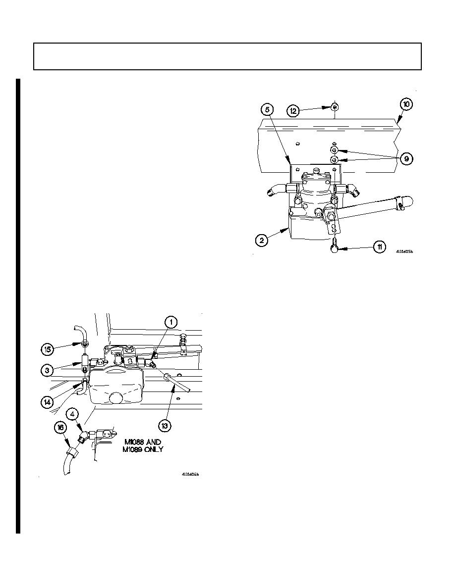
(CONT)
NOTE
Perform step (13) on M1088.
Begin by using holes furthest left on
crossmember. Final position will be determined
during load sensing valve adjustment.
(13) Position load sensing valve (2), bracket (5) and four
spacers (9) on crossmember (10) with two screws (11),
and self-locking nuts (12).
(14) Connect air hose (13) to 45-degree fitting (1).
NOTE
Perform step (15) on all models except
M1088.
(15) Connect air hoses (14 and 15) to tee fitting (3).
NOTE
Perform step (16) on M1088 and M1089.
(16) Connect air hose (16) to 45-degree fitting (4).
11-64
Change 1
