
TM 9-2320-272-24-4
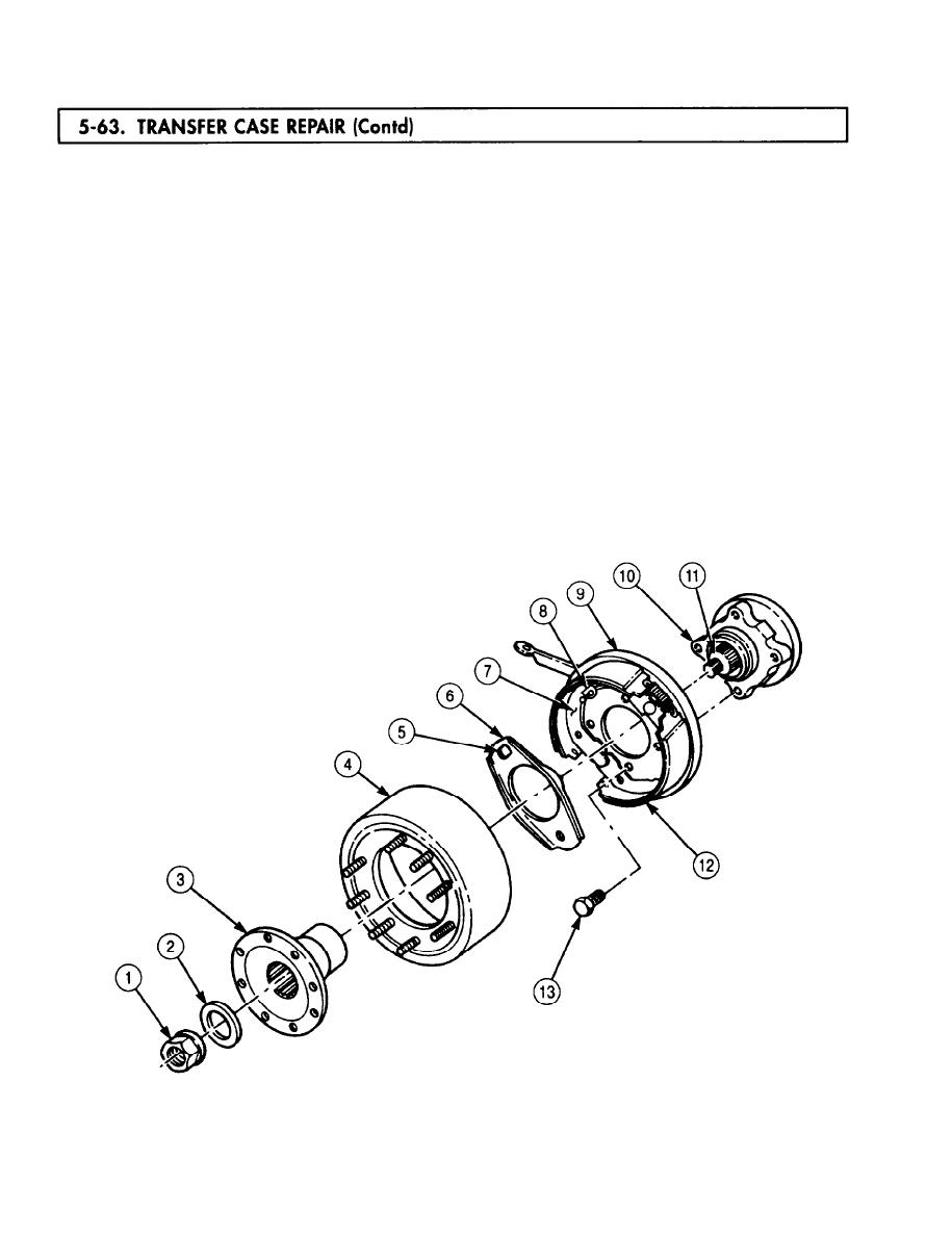
93.
Install brakeshoe assembly (12) and dust cover (9) on companion flange (10) with four
screws (13). Tighten screws (13) 180-230 lb-ft (244-312 Nm).
Position actuating plate (6) against backing plate (7) so retainer opening (5) fits over brake lever
94.
stud (8) of backing plate (7).
NOTE
Apply GAA grease to inside diameter of all seals.
Install parking brake drum (4) and output flange (3) on output shaft (11).
95.
Apply a thin coating of gasket sealant to mating surfaces of washer (2) and install washer (2) and
96.
new locknut (1) on output shaft (11). Tighten locknut (1) 450-600 lb-ft (610-814 Nm).
Remove nut (18), washer (17), screw (16), washer (17), screw (14), washer (19), and chain from main
97.
input flange (20) and front output flange (15).
Apply a thin coating of gasket sealant to mating surfaces of inspection plate (24) and transfer
98.
case (23) and install inspection plate (24) on transfer case (23) with eight screws (25). Do not tighten
screws (25).
Using crowfoot wrench, install pushrod (22) and interlock air cylinder (21) on transfer case (23).
99.
Tighten interlock air cylinder (21) 30-40 lb-ft (41-54 Nm).
5-430
