
TM 9-2320-260-34-2
APPENDIX E (Contd)
MATERIALS
ITEM
NSN
DESCRIPTION
REQ'D
NO.
Bolt: MS90728-171
1
4
Bolt Guide: 6-5/32 x 1-1/2 x 1-1/2, MS14296H405
1
5
Bolt Guide Support:
2
2
5-15/16 X 1-3/4 x 3/8, MS14296H389
Cover, Rear Output Shaft: 8758288
1
1
1
Gage Support: 1-1/2 x 1-1/8 x 3/16, MS14296H405
6
Flange Nut, Slotted Head: MS35692-1
1
8
Mounting Plate: 2-1/16 x 1-5/8 x 3/8, MS14296H369
1
9
Nut: MS51922-49
2
3
Screw, Cap, Socket Head: MS16997-70
7
6
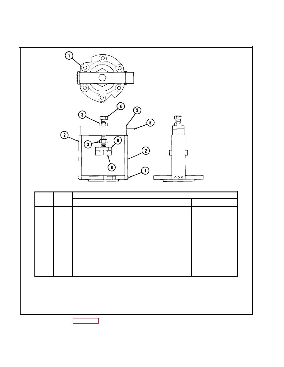
PROCEDURE
1. Assemble rear output shaft adjusting fixture using materials and diagram above.
2. Attach two bolt guide supports (2) to cover (1) with six socket head capscrews (7).
3. Thread upper nut (3) onto bolt (4). Thread bolt (4) into bolt guide (5) and gage support (6).
Thread lower nut (3), mounting plate (9), and flange nut (8) on bolt (4).
E-4
