
idling, c o n n e c t t h e a m m e t e r a n d v o l t m e t e r a s
shown in figure 2-21.
(2) Turn o n t h e l o a d s w i t c h ; w a t c h the
(5) If the regulator meets the requirements in
the voltage control and amperage control tests--
ammeter and voltmeter. If the voltage drops and
27.5 to 29 volts and 23 to 27 amps--it is regulating
t h e amperage shows o n meter, turn the control
correctly. The cutout switch must still be checked.
knob until the voltage reads at least 23 volts and
the low amperage is shown on the meter.
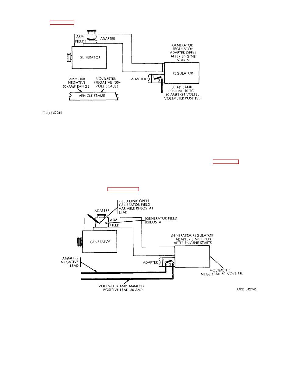
c. L i n e S w i t c h C u t o u t .
{3) Run the engine at 1000 to 1200 rpm.
(1) C o n n e c t t h e v o l t m e t e r , a m m e t e r , a n d
variable rheostat as shown in figure 2-22. Turn the
Turn the control knob until the ammeter reads 24
field rheostat fully counterclockwise, or to its off
to 27 amps. The voltmeter should start dropping at
position.
that point. and the ammeter should remain at 24 to
2 7 amps.
(4) If the ammeter exceeds 27 amps or reads
below 23 amps, replace the regulator (para 2-132).
2-22. Generator regulator line switch cutout test hookup.
(2) With the field link on t h e generator
the ammeter and voltmeter. The reading should be
adapter open and the link on the regulator open,
below 10 volts and no amperage reading.
bring the engine to 1000 to 1200 rpm, and observe
(3) Turn the field rheostat clockwise until the
