
TM 9-2320-366-20-5
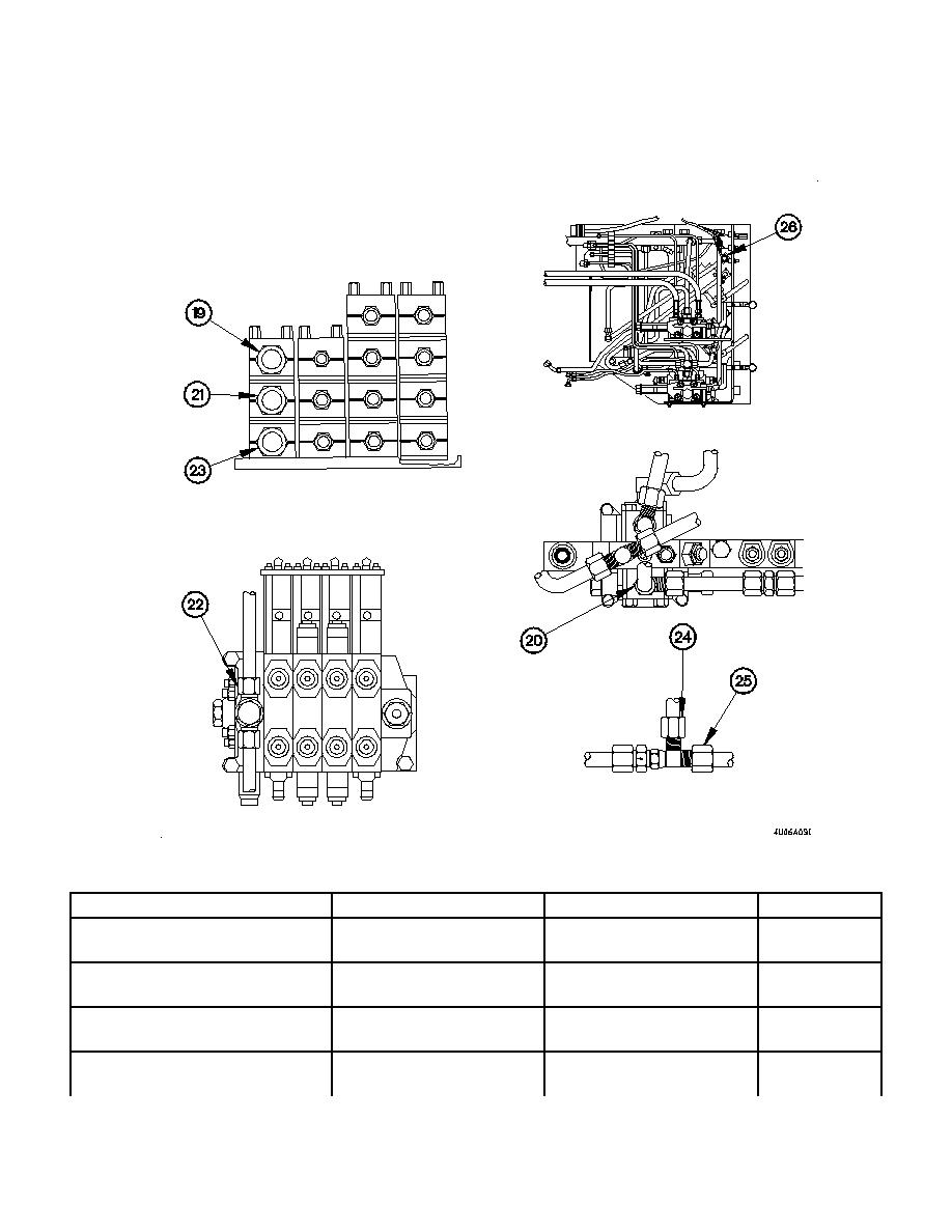
Figure 19-2. M1089 Wrecker Control Panel Pressure and Function Hydraulic Hose and Tubing Locations (Cont)
Table 19-2. M1089 Wrecker Control Panel Pressure and Function Hydraulic Hose and Tubing Locations (Cont)
Hydraulic Hose or Tube Name
From
To
Circuit "A" Pressure Tube
Union (19)
Slave/External Power
39-88 lb-ft
Valve Fitting (20)
(49-119 Nm)
Circuit "B" Pressure Tube
Union (21)
Four function manual
39-88 lb-ft
control valve fitting (22)
(49-119 Nm)
Circuit "C" Pressure Tube
Union (23)
Three way tee fitting (24)
39-88 lb-ft
(49-119 Nm)
Mode Select Pressure Tube
Three way tee fitting (25)
Mode selector manual
39-88 lb-ft
control valve fitting (26)
(49-119 Nm)
19-27
