
TM 9-2320-366-20-5
This task covers:
a. Removal
c. Follow-On Maintenance
b. Installation
INITIAL SETUP
Equipment Conditions
Materials/Parts
Batteries disconnected (para 7-57).
Dispenser, Pressure Sensitive Adhesive Tape
CTIS ECU removed (para 12-6).
(Item 20, Appendix D)
Nut, Self-Locking (3) (vehicle serial numbers
0001 through 3696 equipped with original
Tools and Special Tools
Tool Kit, Genl Mech (Item 46, Appendix C)
personnel heaters) (Item 177, Appendix G)
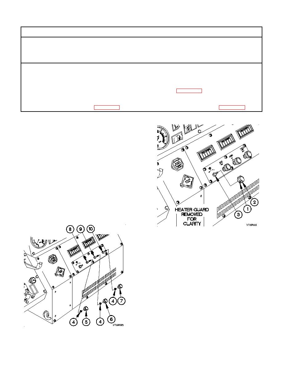
a. Removal.
(1) Loosen two setscrews (1) in heater fan control switch
knob (2).
(2) Remove heater fan control switch knob (2) from heater
fan control switch (3).
NOTE
Perform steps (3) and (5) on vehicle serial
numbers 0001 through 3696 equipped with
original personnel heaters.
(3) Loosen three self-locking nuts (4) on knobs (5, 6, and 7).
(4) Remove knobs (5, 6, and 7) from HEAT control cable
(8), VENT control cable (9), and DEFR control cable
(10).
(5) Remove three self-locking nuts (4) from HEAT control
cable (8), VENT control cable (9), and DEFR control
cable (10). Discard self-locking nuts.
