
TM 9-2320-272-24-4
90.
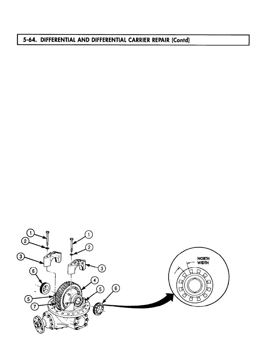
Position two caps (3) on saddles (5) and install with four washers (2) and screws (1). Finger-tighten
screws (1).
91.
Start two adjusting nuts (6) in threads of saddles (5) and caps (3). Move caps (3) as necessary to
align threads to adjusting nuts (6).
92.
Turn adjusting nuts (6) by hand until contact is made with races (4).
93.
Ensure helical ring gear (7) aligns with mating helical pinion gear (9). If necessary, loosen and
tighten adjusting nuts (6) to align gears.
94.
Tighten screws (1) 7-12 lb-ft (9-16 Nm).
NOTE
Ensure a notch of each adjusting nut aligns with top center of cap.
95.
To establish helical bearing preload, perform step a. or b.
a. Alternately tighten adjusting nuts (6) a total 1.5 to 2.75 notch widths.
b. Tighten each adjusting nut (6) 15-35 lb-in. (1.7-4.0 Nm).
96.
Install dial indicator on differential carrier housing (8) with indicator plunger perpendicular to edge
of helical ring gear (7).
97.
Turn helical ring gear (7) one revolution in each direction. Runout reading on dial indicator must
not exceed 0.008 in. (0.20 mm). If runout exceeds this value, loosen adjusting nuts (6) and screws (1)
and repeat steps 90 through 95.
98.
Reposition dial indicator so plunger contacts tooth (10) and detects motion in plane of rotation of
helical ring gear (7) as the gear rotates.
99.
Hold helical pinion gear (9) still and rock helical ring gear (7) back and forth. Observe backlash
reading on dial indicator.
106.
Backlash should be 0.005-0.015 in. (0.127-0.381 mm). If reading is outside of these limits, replace
helical ring gear (7) and helical pinion gear (9).
101.
Tighten four screws (1) 290-370 lb-ft (393-502 Nm).
102.
Install two locks (12) of adjusting nut (6) on caps (3) with screws (13). Tighten screws (13)
66-85 lb-ft (90-115 Nm).
103.
Install new safety wire (11) through four screws (1) and two screws (13). Twist safety wire (11) ends
together, cut off and discard excess safety wire (11), and bend twisted ends of safety wire (11) out
of way.
5-460
