
Table 2-4. Electrical Troubleshooting (Contd).
MALFUNCTION
TEST OR INSPECTION
CORRECTIVE ACTION
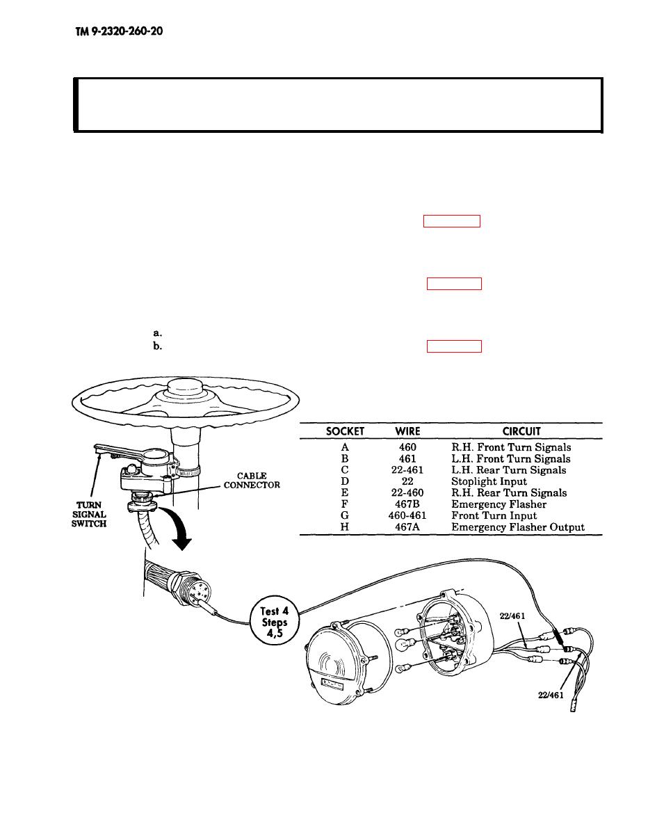
Test 5. Test continuity of turn signal switch.
Step 1. Disconnect cable connector at turn signal switch.
Step 2. Place turn signal switch to LEFT position.
Step 3. Touch negative lead of multimeter to pin G of turn signal switch.
Step 4. Touch positive lead of multimeter to pin B (front left) and pin C (left rear) of turn signal
switch. Continuity should be present.
Replace turn signal switch if continuity is not present (para. 4-33).
Step 5. Place turn signal lever to RIGHT position.
Step 6. Touch negative lead of multimeter to pin G of turn signal switch.
Step 7. Touch positive lead of multimeter to pin A (right front) and pin E (right rear) at turn
signal switch. Continuity should be present.
If continuity is not present, replace turn signal switch (para. 4-33).
Step 8. Touch negative lead of multimeter to pin G of turn signal switch.
Step 9. Touch positive lead of multimeter to pin F at turn signal switch. Continuity should be
present.
If continuity is present, go to malfunction 25, test 2.
If continuity is not present, replace turn signal switch (para. 4-33).
END OF TESTING!
2-137
