
TM 9-2320-272-24-4
1.
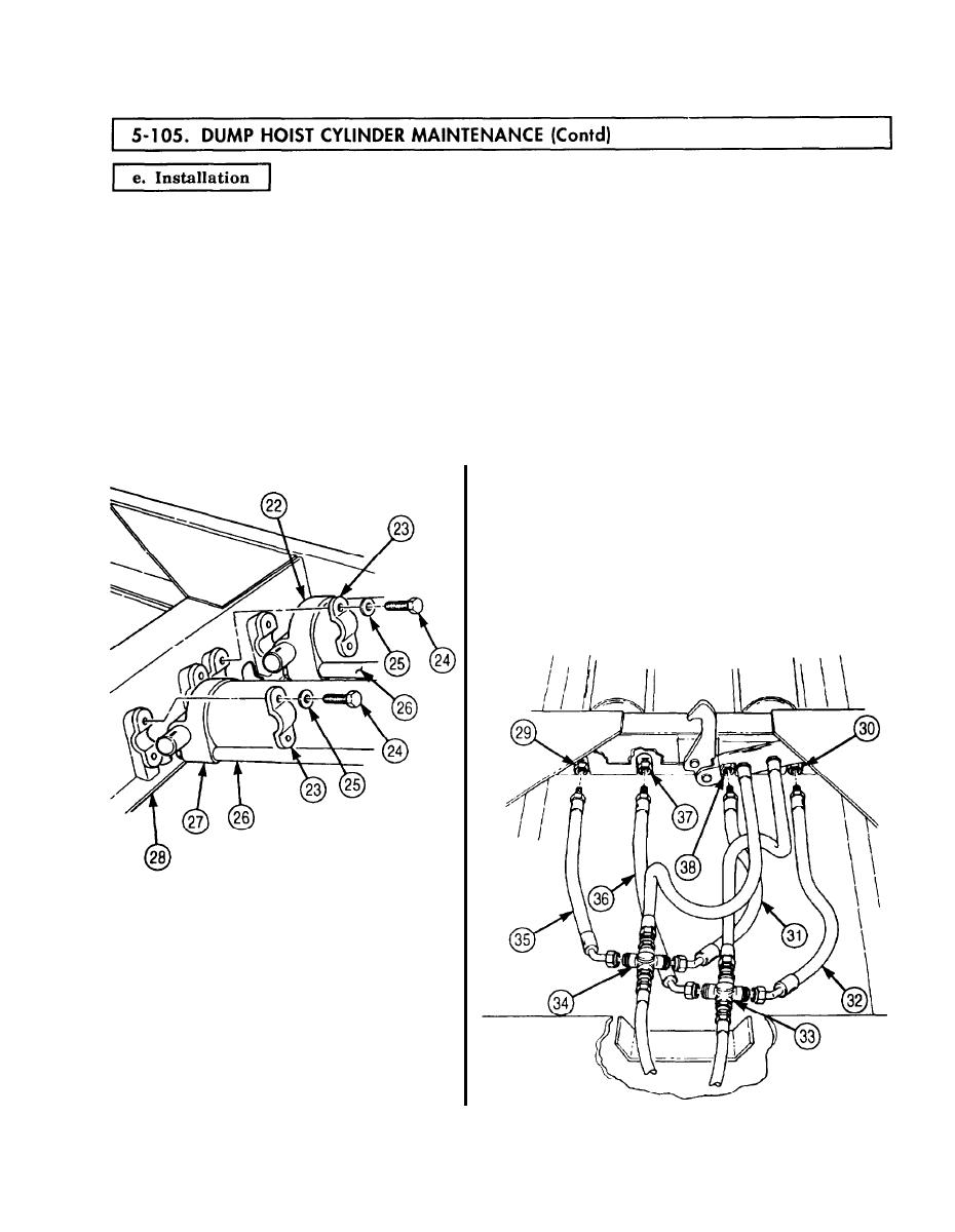
Position hoist cylinders (27) and (22) on subframe (28) with bypass tubes (26) facing down.
2.
Install each hoist cylinder (27) and (22) with two bearing caps (23), four new lockwashers (25), and
screws (24).
NOTE
To properly identify hose connection points, the cylinder port with
bypass tube extending to the middle of the cylinder will be
identified as port B. The cylinder port with bypass tube extending
full length of the cylinder will be identified as port A.
3.
Connect hydraulic hoses (31) and (35) to left cylinder port A (38), right cylinder port A (29), and
right cross fitting (34).
4.
Connect hydraulic hoses (32) and (36) to left cylinder port B (30), right cylinder port B (37), and left
cross fitting (33).
5-623
