TM 9-2320-272-24-2
1.
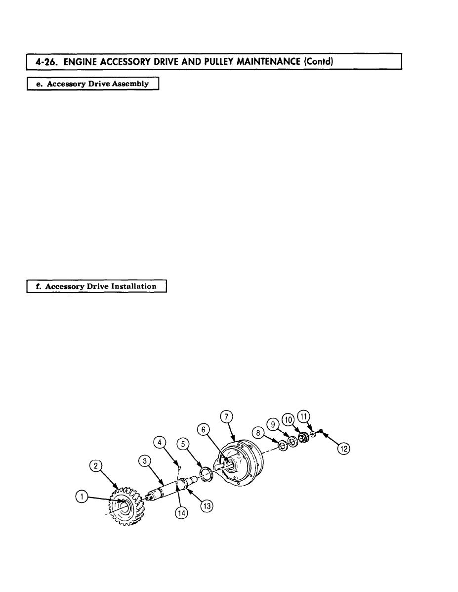
Install new dowel pin (4) in hole (14) of driveshaft (3).
NOTE
Remaining dowel pin is installed with accessory drive pulley.
2.
Align slot (1) in bore of drive gear (2) with dowel pin (4) and press drive gear (2) on driveshaft (3)
over dowel pin (4). Ensure drive gear (2) is seated on shoulder (13).
3.
Install large thrust washer (5) on front of accessory drive housing (7).
4.
Install driveshaft (3) and drive gear (2) through thrust washer (5) and bushing (6) in accessory drive
housing (7).
5.
Install thrust washer (8) over driveshaft (3) and position in accessory drive housing (7). Ensure
grooved side of thrust washer (8) faces away from accessory drive housing (7).
6.
Install washer (9) on driveshaft (3) against thrust washer (8).
NOTE
Ensure flat end of coupling halfshaft faces away from accessory
drive housing.
7.
Press coupling halfshaft (10) on driveshaft (3) until flush with end.
8.
Measure driveshaft (3) end play. End play should be 0.002-0.012 in. (0.05-0.26 mm). If end play is
not within limits, press driveshaft (3) through coupling halfshaft (10) to obtain proper end play.
9.
Install washer (11) and screw (12) on driveshaft (3). Tighten screw (12) 30-35 lb-ft (41-47 Nm).
NOTE
If accessory drive gear and camshaft gear are not properly aligned,
valve, injector, and compressor timing will be incorrect.
1.
Remove pipe plug (20) from front gearcase cover (18).
2.
Rotate crankshaft (17) to No. 1 piston Top Dead Center (TDC) firing stroke.
3.
Rotate crankshaft (17) 90 degrees past TDC.
4.
Install accessory drive housing (23) and new gasket (22) on engine block gearcase (21) with five
new screw-assembled lockwashers (24). Ensure timing marks (19) on accessory drive gear (15) and
camshaft gear (16) align. Tighten screw-assembled lockwashers (24) 40-45 lb-ft (54-61 Nm).
5.
Wrap pipe plug (20) threads with antiseize tape and install in front gearcase cover (18).
4-190


