TM 9-2320-272-24-2
Table 4-1. Mechanical Troubleshooting (Contd).
MALFUNCTION
TEST OR INSPECTION
CORRECTIVE ACTION
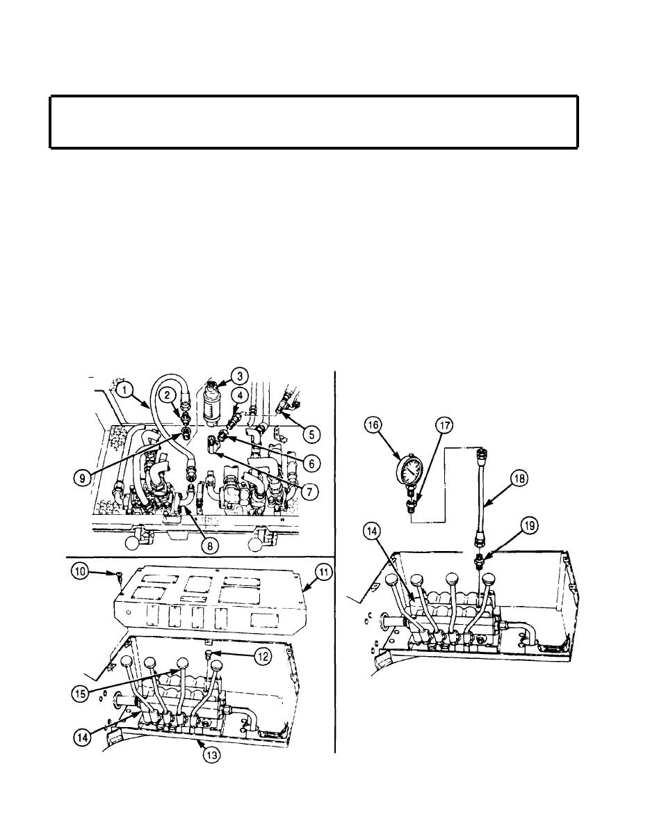
Install appropriate hose assembly (1) on rear winch control valve elbow (8).
e.
Install appropriate elbow (7), reducer (6), and connector (4) on flowmeter (Appendix E,
f.
Item 170) (3), then install flowmeter (3) on tee (5).
g. Install appropriate reducer (9) and adapter (2) on flowmeter (3).
h. Connect hose assembly (1) to adapter (2).
Step 9. Install pressure gauge (Appendix E, Item 168) on boom control valve.
a. Remove five screws (10) and mounting plate (11) from gondola (13).
b. Place crowd control lever (15) in EXTEND position.
NOTE
Have drainage container ready to catch oil.
c. Remove plug (12) from directional control valve (14).
d. Install appropriate connector (19), hose (18), connector (17), and pressure gauge (16) on
directional control valve (14).
4-24


