
T M 9-2320-260-34-2
16-32. HYDRAULIC SWIVEL VALVE REPLACEMENT (M819)
THIS TASK COVERS:
a. Removal
b. Installation
INITIAL SETUP
MATERIALS/PARTS
APPLICABLE MODELS
Antiseize tape (Appendix C, Item 50)
M819
Cap and plug set (Appendix C, Item 6)
TOOLS
REFERENCES (TM)
General mechanic's tool kit
LO 9-2320-260-12
(Appendix B, Item 1)
1-1/16-in. open-end wrench
TM 9-2320-260-10
TM 9-2320-260-34P-2
1-1/2-in. open-end wrench
EQUIPMENT CONDITION
q Parking brake set (TM 9-2320-260-10).
1-11/16-in. open-end wrench
Boom raised and supported (TM 9-2320-260-10).
q Hydraulic oil tank drained (LO 9-2320-260-12).
Lifting device
Chains
CAUTION
Clean area around hoses and lines before removal to prevent
entry of dirt. Damage will occur if dirt or dust enters system.
Cap or plug all openings immediately after disconnecting lines
and hoses to prevent contamination. Remove caps and plugs
prior to installation. Failure to do so may result in damage to
hydraulic system.
NOTE
l Tag hoses for installation.
. Have drainage container ready to catch oil.
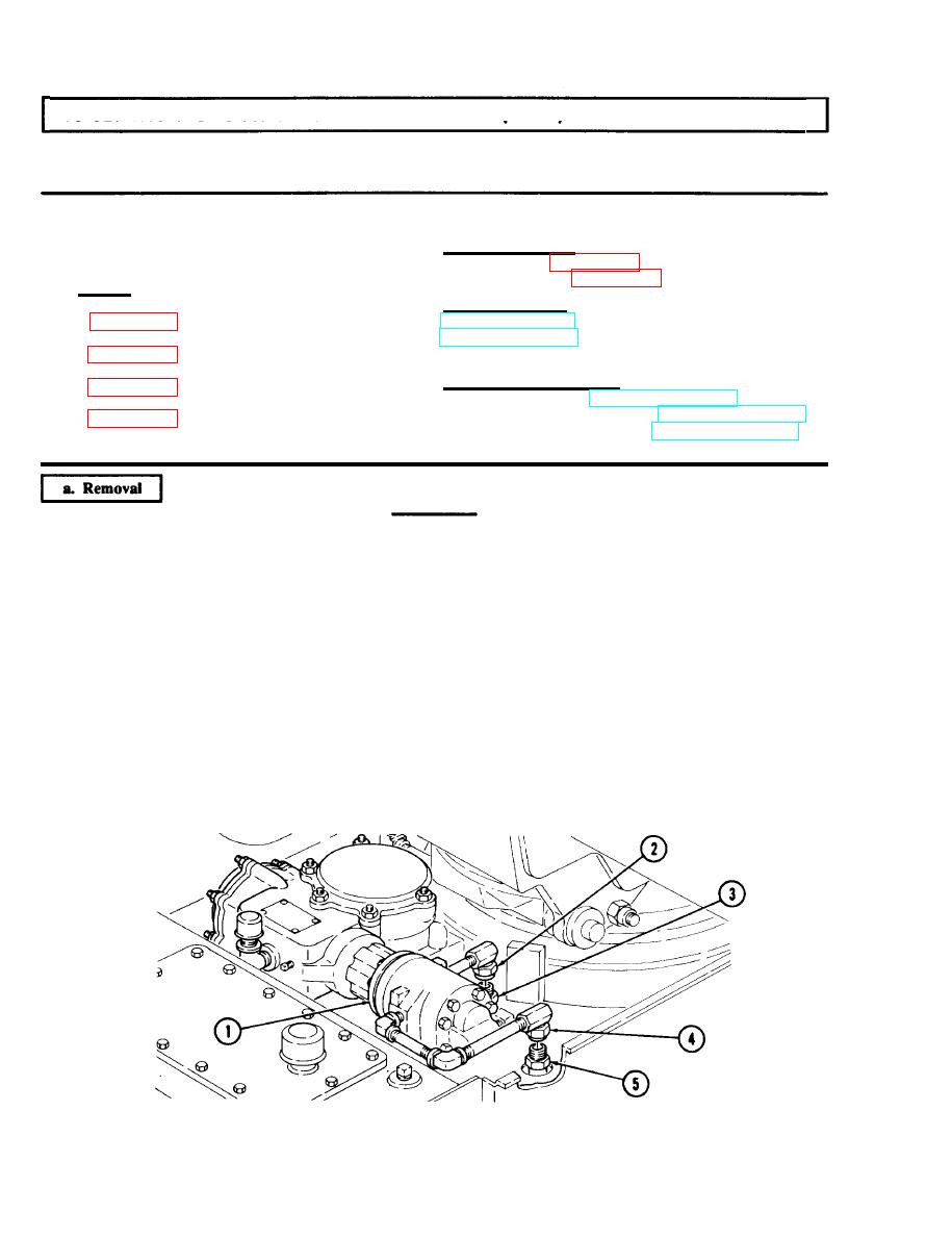
1. Disconnect hoses (3) and (5) from elbows (2) and (4) on swing motor (1).
2. Disconnect return hose (9) from coupling (8) on 45 degree elbow (7).
3. Disconnect pressure hose (10) from coupling (11) on relief valve (12).
4. Disconnect drain hose (13) from elbow (14) at hydraulic oil reservoir (6).
5. Remove seven screws (18) and cover (19) from mounting brackets (23).
6. Disconnect drain hose (21) from coupling (20) on control valve bank (22).
7. Disconnect drain hose (16) from elbow (15) on hoist winch motor (17).
16-182
