
TM 9-2320-260-20
THIS TASK COVERS:
a. Removal
b. Installation
INITIAL SETUP
APPLICABLE MODELS
EQUIPMENT CONDITION
M820, M820A1, M820A2
Parking brake set (TM 9-2320-260-10).
Battery ground cable disconnected (para. 4-48).
REFERENCES (TM)
TM 9-2320-260-10
TM 9-2320-260-20P
NOTE
Tag all wires for installation.
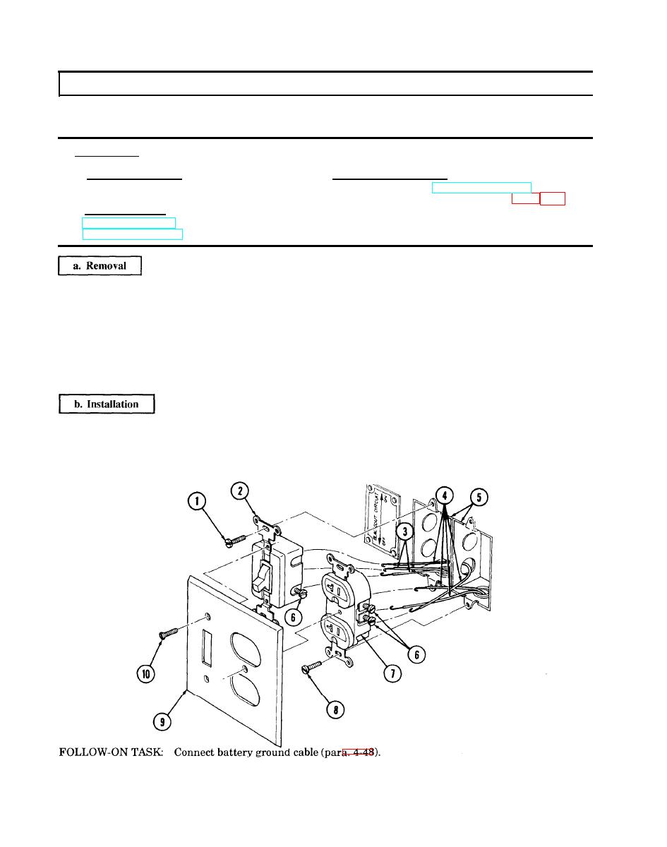
1. Remove three screws (10) and cover plate (9) from switch (2) and receptacle (7).
2. Remove two screws (1) and switch (2) from junction box (5).
3. Remove two screws (8) and receptacle (7) from junction box (5).
4. Loosen five screws (6) and disconnect two wires (3) and four wires (4) from switch (2) and
receptacle (7).
1. Connect two wires (3) and four wires (4) to switch (2) and receptacle (7) and tighten five screws (6).
2. Install receptacle (7) in junction box (5) with two screws (8).
3. Install switch (2) in junction box (5) with two screws (1).
4. Install cover plate (9) on receptacle (7) and switch (2) with three screws (10).
