
Table 2-4. Electrical Troubleshooting (Contd).
MALFUNCTION
TEST OR INSPECTION
CORRECTIVE ACTION
32. VOLTMETER GAGE INOPERATIVE
NOTE
If STE/ICE is available, perform NG31 - gage test (chapter 2,
section VII).
Test 1. Test voltmeter gage.
Step 1. Turn battery switch to ON position.
Step 2. Turn ignition switch to RUN position. Do not start engine.
Step 3. Voltmeter indicator should rest between lower edge of GREEN area and upper edge of
YELLOW area on gage (24 volts).
Step 4. Start engine (TM 9-2320-260-10) and observe voltmeter on instrument cluster.
Step 5. Voltmeter indicator should rise as engine speeds up and stop over white dot in green
area (approximately 28.0 volts).
If voltmeter does not perform as specified in steps 3 and 5 above, stop engine and go to
test 2.
Test 2. Test battery voltage to voltmeter. Go to malfunction 29, test 2.
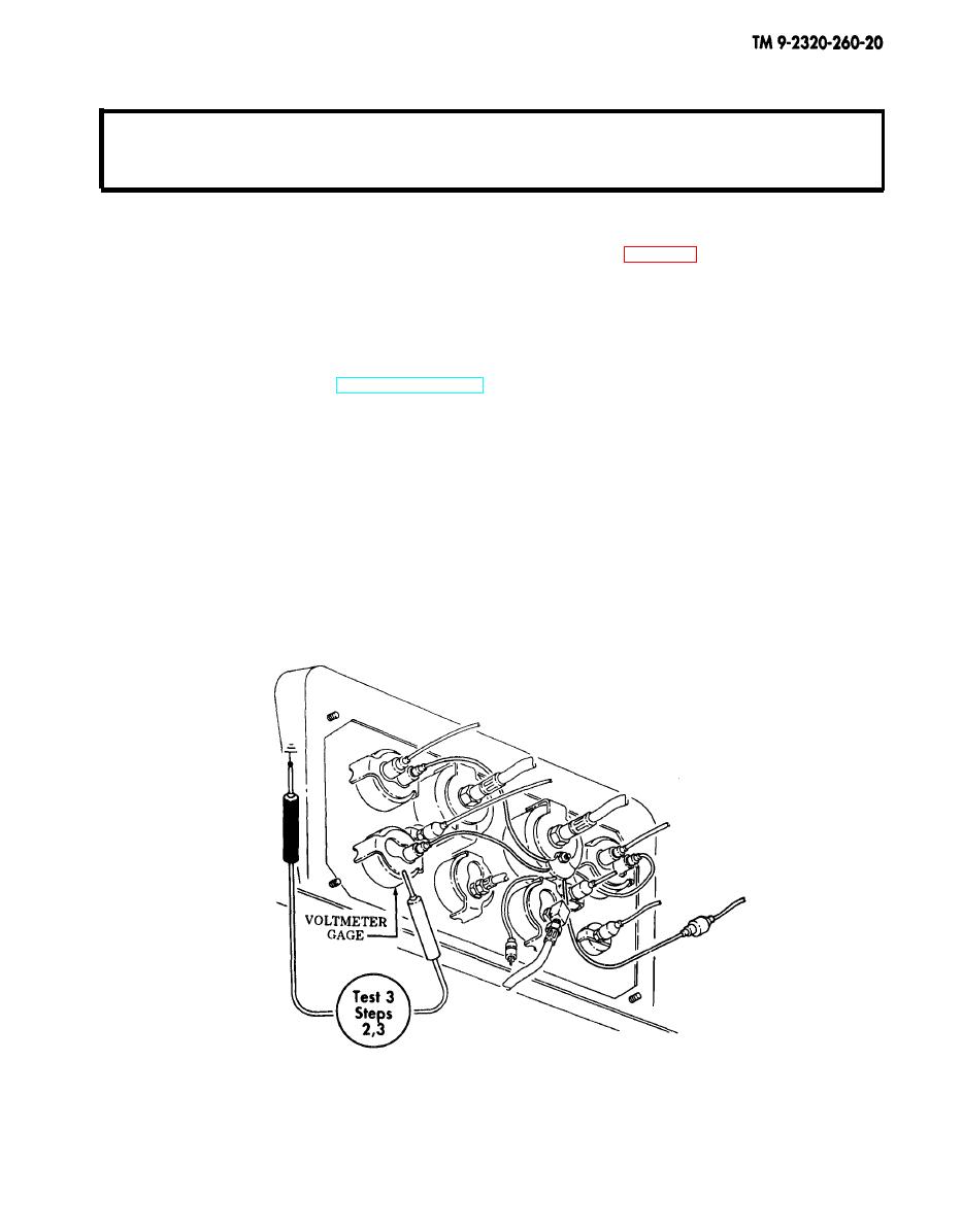
Test 3. Check frame ground to multimeter.
Step 1. Set multimeter to RX1 scale.
Step 2. Touch negative lead of multimeter to panel ground on instrument cluster.
Step 3. Touch positive lead of multimeter to voltmeter gage bracket. Continuity should be
present. Make sure instrument panel is grounded.
a. If continuity is present, recheck gage operation.
b. If continuity is not present, remove voltmeter and check for corrosion around
voltmeter body.
END OF TESTING!
2-159
