• Home
  • Download PDF
  • Order CD-ROM
  • Order in Print
Figure 6-3, Lifting diagram for M52 with six-wire sling and one spreader bar.
Table 6-1, Bill of MateriaL for Blocking and Tiedown of Typical 5-Ton, 6x6 Truck in Hold of General Cargo Vessel (fig 6#5).

TM-55-2320-211-15-1 Transportability Guidance Truck 5-Ton 6x6 M39 Series Chassis Truck Dump: M51 M51A1 M51A2 Truck Tractor: M52 M52A1 M52A2 Manual
Page Navigation
  39    40    41    42    43  44  45    46    47    48    49  
Figure 6-4. Lifting diagram for M291A2 with eight-wire sling and two spreader bars.
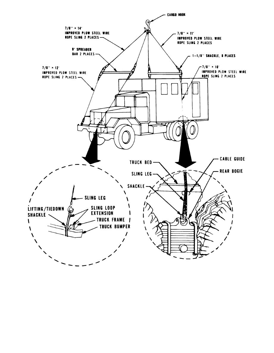
sling leg is passed through the cable guide attached to the
CAUTION
bottom outside edge of the cargo body, to eliminate the
possibility of lifting slings shifting during lifting operations.
The two front shackles on top of the front bumper
The rear sling-leg eyes are attached directly to the pin in
must not be used for lifting.
the spring saddle with a shackle. Typical lifting diagrams
are shown in figures 6-1 through 6-4.
(2) The rear lifting points are located on the spring
b. Loading, Vehicles are always loaded onto vessels in
saddle and pin assembly located on top of the rear springs.
their minimum configuration-that is, reduced height, with
Bodies are reinforced near the spring and pin assembly. The
6-5
Change 1


Western Governors University

Privacy Statement
Press Release
Contact

© Copyright Integrated Publishing, Inc.. All Rights Reserved. Design by Strategico.