
TM 9-2320-272-24-4
47.
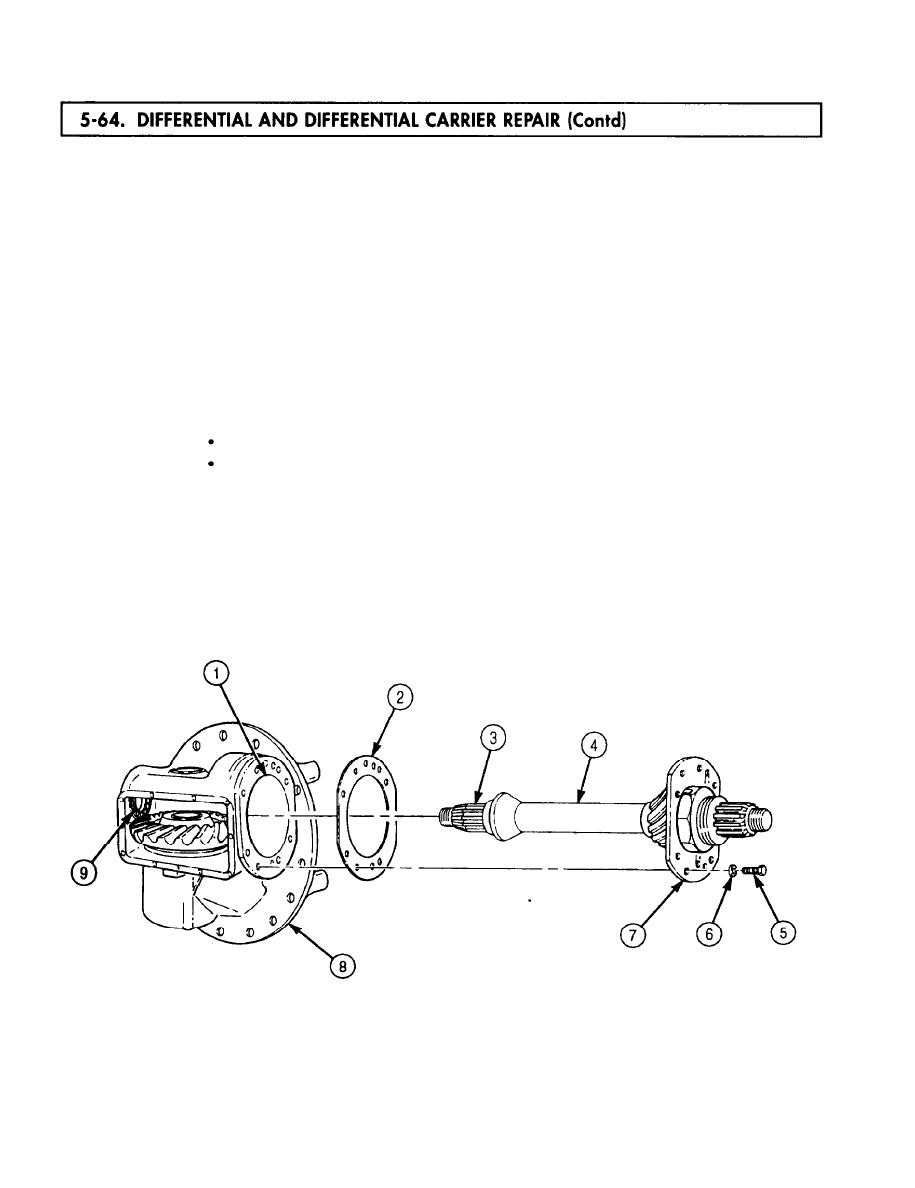
Position shims (2), same thickness pack as removed, on retainer (7) and slide mainshaft (4) into
differential carrier housing (8). Align inner race (3) with rear roller bearing (9).
Align holes in shims (2), differential carrier housing (8), bore (1), and retainer (7) and install with
48.
eight washers (6) and screws (5). Tighten screws (5) 93-120 lb-ft (126-163 Nm).
CAUTION
Correct bevel ring gear and pinion gear contact pattern is critical
to correct operation of differential and differential carrier
assembly. Incorrect contact pattern can result in noisy operation or
premature failure of these two gears.
Check bevel ring gear (10) and pinion gear (11) tooth contact pattern by applying blue oil-base
49.
pigment to at least three teeth of clean bevel ring gear (10). Turn mainshaft (4) for three full
rotations of bevel ring gear (10).
Examine teeth contact pattern (13) of bevel ring gear (10) with pinion gear (11). Pattern should be
50.
centered both ways on teeth (12) and cover over two-thirds of tooth (12) contact surface.
NOTE
If pattern is not correct, perform steps 51 through 69.
If pattern is correct, go to step 71.
51.
If contact pattern resembles pattern (14), perform steps 55-59 and 63-69.
52.
If contact pattern resembles pattern (15), perform steps 55-58, 60, and 63-69.
53.
If contact pattern resembles pattern (16), perform steps 55-58, 61, and 63-69.
54.
If contact pattern resembles pattern (17), perform steps 55-58, 62, and 63-69.
5-452
