
TM 9-2320-272-24-4
5-6. FUEL INJECTOR SLEEVE MAINTENANCE (Contd)
5.
Size, grind, and inspect injector sleeve seat cutter (5) and ensure it is ground to exact contours
listed in table 5-3.
NOTE
Use a solid stream of clean cutting oil to allow injector sleeve
seat cutter to cut freely without grabbing.
Proper seating and protrusion of injector sleeve seat cutter are
checked in task e.
6.
Install injector sleeve seat cutter (5) on head (6) and use in drill press with pilot (4) to cut injector
sleeve (2) just enough to provide for proper seating of injector and to maintain correct injector tip
protrusion.
e. Check and Test
NOTE
Steps 1 through 4 check injector cup seating pattern in injector.
1.
Apply light coat of Prussian blue to injector cup (11) and install injector assembly (9) into cylinder
head (1) with washer (10), clamp (8), and two screws (7). Tighten screws (7) alternately in
4lb-ft (5 Nm) steps to l0-12 lb-ft (14-16 Nm).
2.
Remove two screws (7), clamp (8), washer (l0), and injector assembly (9) from cylinder head (1).
Check seat pattern in bottom of injector sleeve (2) cup seating area.
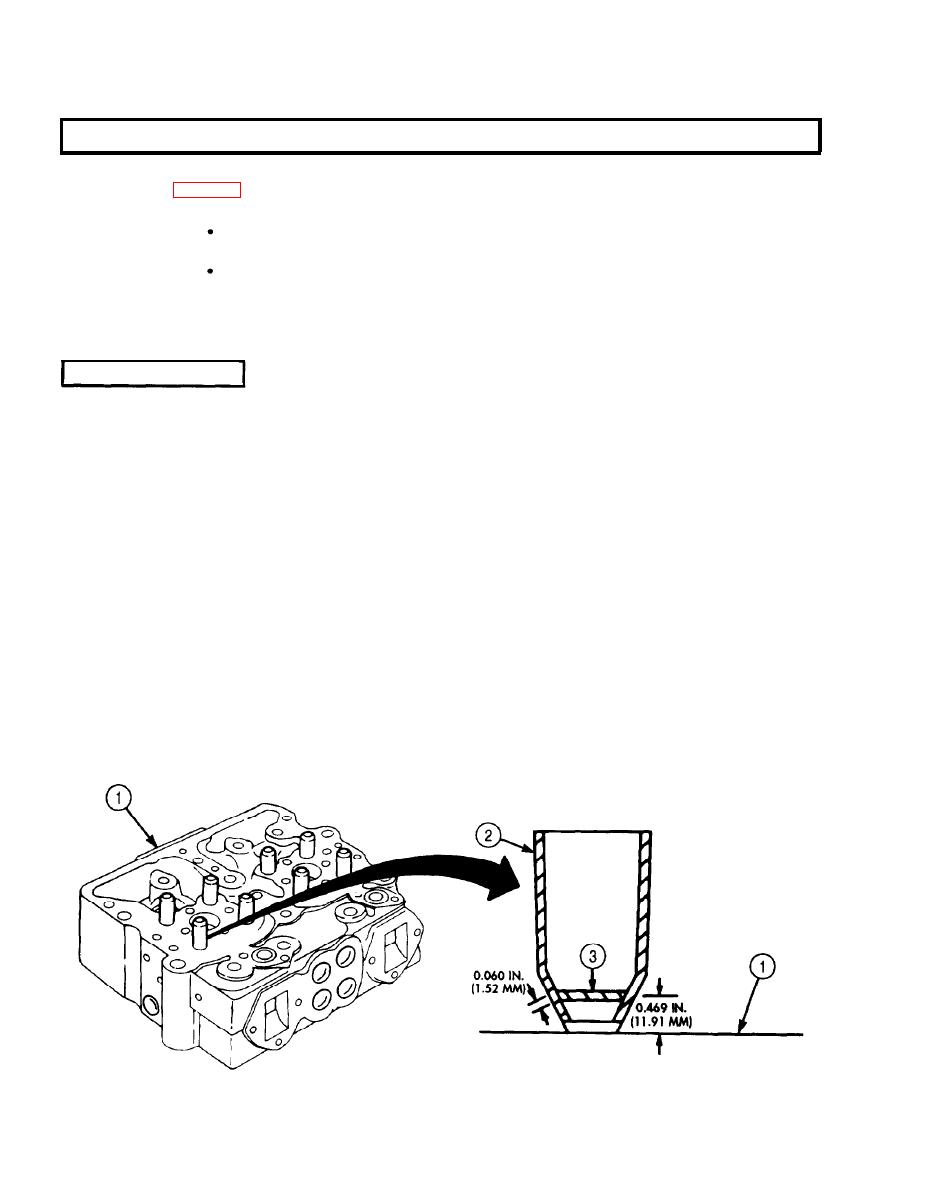
3.
If blued band (3) on injector sleeve (2) seating area is not at least 0.060 in. (1.52 mm) wide and
4.
located approximately 0.469 in. (11.91 mm) from bottom of cylinder head (1) surface, regrind
injector sleeve (2) seating area as described in steps 5 and 6 of task f.
5.
Install injector assembly (9) in injector sleeve (2) in injector head (1) with clamp (8), washer (10),
and two screws (7). Tighten screws (7) alternately in 4 lb-ft (5 Nm) steps to 10-12 lb-ft. (14-16 Nm).
6.
Check protrusion of injector tip (13) using dial indicator (12).
a. If injector tip (13) protrusion exceeds 0.070 in. (1.78 mm), install new injector sleeve (2).
b. If injector tip (13) protrusion is less than 0.060 in. (1.52 mm), regrind injector sleeve (2).
5-32
