
TM 9-2320-272-24-1
3-41. ACCELERATOR PEDAL, BRACKET, ROD, AND STOPSCREW REPLACEMENT
THIS TASK COVERS:
b. Installation
a. Removal
INITIAL SETUP:
APPLICABLE MODELS
REFERENCES (TM)
All
TM 9-2320-272-10
TM 9-2320-272-24P
TOOLS
General mechanic's tool kit (Appendix E, Item 1)
EQUIPMENT CONDITION
l Parking brake set (TM 9-2320-272-10).
MATERIALS/PARTS
l Left splash shield removed (TM 9-2320-272-10).
Two cotter pins (Appendix D, Item 66)
1.
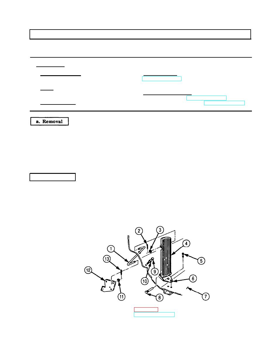
Remove cotter pin (2) and washer (3) from accelerator pedal push rod (1). Discard cotter pin (2).
2.
Remove hinge pin (8) and accelerator pedal (4) from accelerator pedal bracket (6).
3.
Remove two screws (5) and bracket (6) from cab floor (7).
4.
Remove cotter pin (13), washer (ll), and accelerator pedal rod (1) from link assembly (12). Discard
cotter pin (13).
5.
Loosen jamnut (10) above cab floor (7) and remove accelerator pedal stopscrew (9).
6.
Remove jamnut (10) from pedal stopscrew (9).
b. Installation
1.
Install jamnut (10) on pedal stopscrew (9) to limit of threads.
2.
Install pedal stopscrew (9) on cab floor (7) and tighten jamnut (10) against cab floor (7).
3.
Install accelerator pedal bracket (6) on cab floor (7) with two screws (5).
4.
Install accelerator pedal (4) on bracket (6) with hinge pin (8).
5.
Install accelerator pedal push rod (1) on accelerator pedal (4) and link assembly (12) with washers (3)
and (11) and new cotter pins (13) and (2). Spread ends of cotter pins (2) and (13) after adjustment.
FOLLOW-ON TASKS: Adjust accelerator linkage (para. 3-42 or 3-43).
l Install left splash shield (TM 9-2320-272-10).
3-123
