TM 9-2320-260-34-2
16-36. CONTROL VALVE BANK REPLACEMENT (M819) (Contd
NOTE
q Perform steps 13 and 14 if new control valve bank is to be
installed.
q Tag elbows and adapter elbows for installation.
q Record angle positions of fittings for assembly.
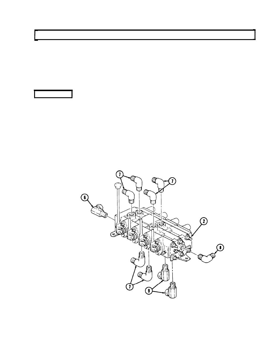
13. Remove elbow (8) and adapter elbow (6) from control valve bank (2).
14. Remove six elbows (7) and two adapter elbows (9) from control valve bank (2).
b. Installation
NOTE
Perform steps 1, 2, and 3 for installation of new control valve bank.
1. Wrap male threads of six elbows (7), two adapter elbows (9), elbow (8), and adapter elbow (6) with
antiseize tape.
2. Install six elbows (7) and two adapter elbows (9) on control valve bank (2) to angles previously
recorded.
NOTE
Elbow and adapter elbow must point to rear of control valve bank
when tightened.
3. Install elbow (8) and adapter elbow (6) on ends of control valve bank (2).
16-221


