TM 9-2320-260-20
Table 2-4. Electrical Troubleshooting (Contd).
MALFUNCTION
TEST OR INSPECTION
INDICATORS, GAGES, AND WARNING SYSTEM
29. All GAGES INOPERATIVE
NOTE
If STE/ICE is available, perform NG231 - gage test (chapter 2,
section VII).
Test 1. Test starter for proper operation.
Step 1. Turn battery switch to ON position.
Step 2. Turn ignition switch to START position.
a. If starter cranks engine, go to test 2.
b. If starter does not crank engine, go to malfunction 2 and troubleshoot starter circuit.
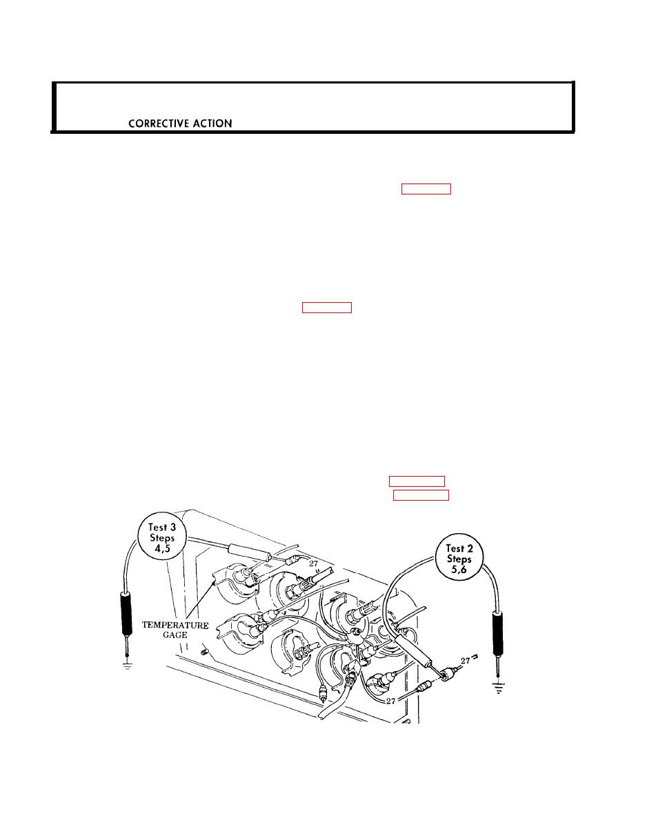
Test 2. Test instrument cluster voltage.
Step 1. Turn ignition switch to OFF position.
Step 2. Remove instrument cluster panel (para. 4-7).
Step 3. Disconnect lead 27 from the instrument cluster.
Step 4. Set multimeter to a range that will measure 24 volts.
Step 5. Touch positive lead of multimeter to contact end of lead 27.
Step 6. Touch negative lead of multimeter to frame ground. Voltage should be present.
a. If battery voltage is present, go to test 3.
b. If battery voltage is not present, go to malfunction 1.
Test 3. Check continuity of instrument cluster harness.
Step 1. Disconnect lead 27 from inoperative gage.
Step 2. Connect jumper wire from instrument panel to a good frame ground.
Step 3. Set multimeter to RX1 scale.
Step 4. Touch positive lead of multimeter to contact end of lead 27.
Step 5. Touch negative lead of multimeter to frame ground. Continuity should be present.
a. Replace instrument gage if continuity is present (para. 4-10).
b. Repair or replace lead if continuity is not present (para. 4-52).
END OF TESTING!
2-152


