
TM 9-2320-272-24-1
Table 2-3. Electrical Troubleshooting (Contd).
MALFUNCTION
TEST OR INSPECTION
CORRECTIVE ACTION
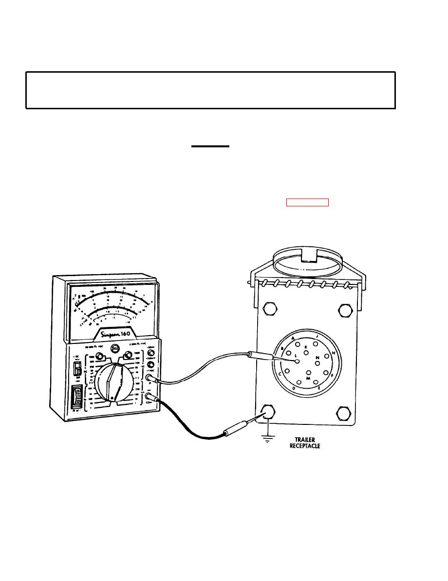
Test 2. Check trailer receptacle ground.
Step 1. Set multimeter on Rx1 for continuity reading.
CAUTION
Lead 15 or wire 15 is hot whenever the batteries are connected.
Step 2. Connect multimeter positive lead to lead 90 at socket (receptacle terminal L and then D)
and negative lead to good ground. Multimeter should indicate continuity from both
terminal L and D to ground.
a. If continuity was indicated, perform malfunction 16, test 4.
b. If continuity was not indicated, repair broken lead 90 (para. 3-131).
END OF TESTING!
2-134

