
TM 9-2320-272-24-1
Table 2-3. Electrical Troubleshooting (Contd).
MALFUNCTION
TEST OR INSPECTION
CORRECTIVE ACTION
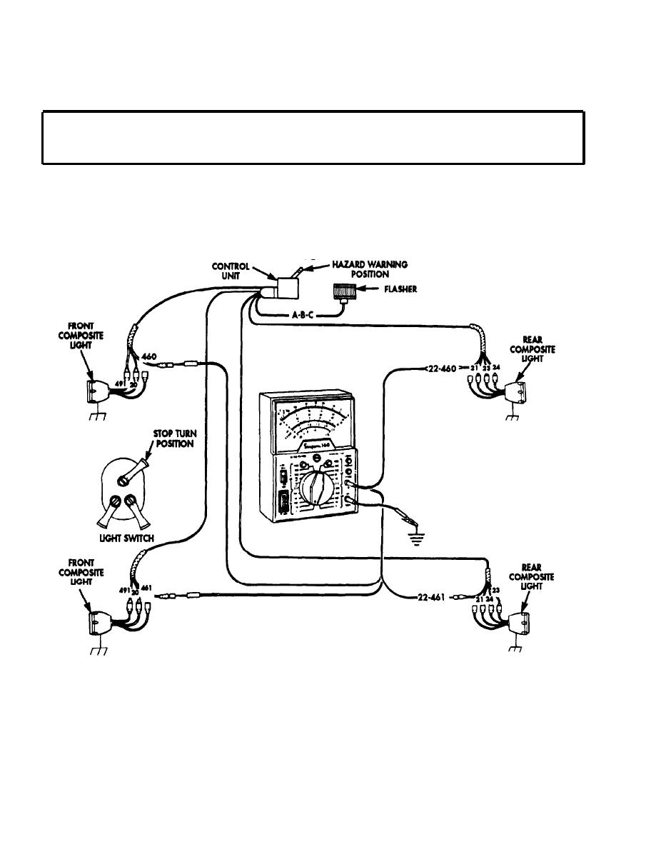
Step 6.
Set multimeter to 50.volt range.
Step 7.
Connect multimeter negative lead to vehicle chassis ground. Touch positive lead to
center contact of leads 460,461, 22-460, or 22-461.
a. Multimeter needle should deflect at a rate of 1 to 2 cycles per second. If multimeter
deflects, clean light socket.
b. If multimeter does not deflect, go to test 3.
Test 3. Test wiring harness continuity.
Step 1. Place battery switch to OFF position.
Step 2. Disconnect wire connector from control unit and disconnect wire from defective light at
lamp base.
Step 3. Place jumper wire from disconnected light wire at light to ground.
Step 4. Set multimeter on RX1 for continuity reading.
Step 5. Connect multimeter negative lead to vehicle chassis ground. Touch positive lead to
control unit harness connector socket point for wire that was jumped to ground.
2-136

