
TM 9-2320-211-20
(2) Remove the hexagon-head setscrew from
2-327. Level Wind
the winch drum, and pull the end of the cable from
the hole in the drum.
a. Removal.
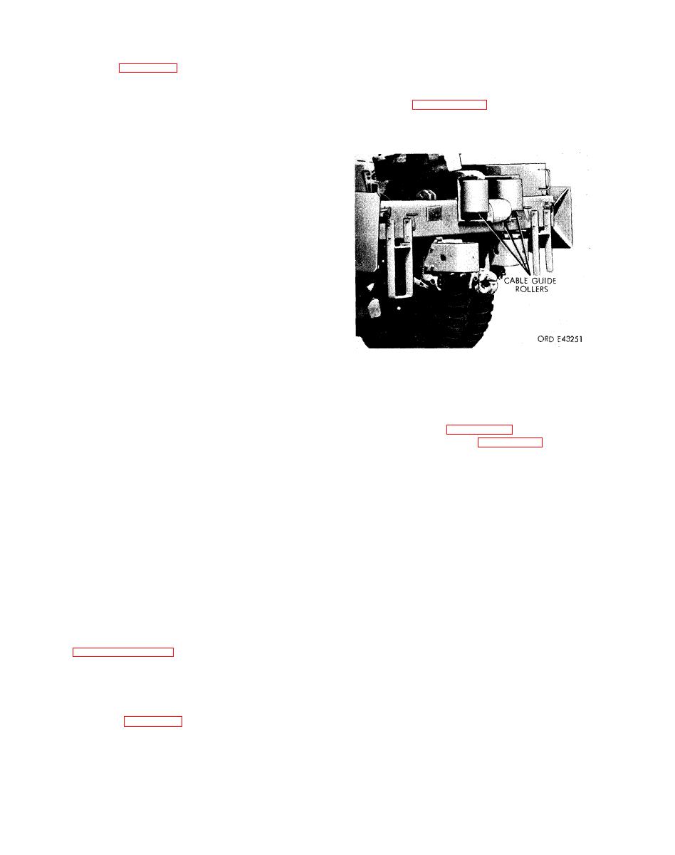
( 3 ) Remove the cable from the level wind
(1) Remove the four capscrews (9) and lock-
sheave (12, fig. 2-268) and guide rollers (fig. 2-
washers (two from each side) securing the cable
275).
guard (10) to the swivel sheave frame.
(2) Remove the winch cable from the swivel
sheave (12), and place the cable around one end of
the trolley track (13).
(3) Replace the cable guard, four lock-
washers, and four capscrews to prevent their loss.
(4) Remove the two capscrews and lock-
washers securing the left end of the level wind to the
end frame (4).
( 5 ) Remove the two cap screws and lock-
washers securing the right end of the level wind to
the gearcase (8).
(6) Lift the level wind (14) off of the winch,
and remove it from the vehicle.
b. Installation.
(1) Position the level wind (14) on top of the
winch, and aline the level wind mounting holes.
(2) Install the two capscrews and lockwashers
in the holes in the right end of the level wind and
gearcase (8). Install the two capscrews and lock-
washers in the holes in the left end of the level wind
and end frame (4). Tighten the cap screws to 80-
100 ft.-lb. torque.
b. Installation.
( 3 ) Remove the four cap screws and lock-
(1) Pass the cable between the upper and
washers, securing the cable guard (10) to the swivel
lower guide rollers (fig. 2-275), and over the level
sheave frames (11), and remove the cable guard.
wind swivel sheave (12, fig. 2-268).
(4) Place the winch cable in the swivel sheave
(2) Insert the end of cable in hole in the winch
g r o o v e , position the cable guard on the swivel
drum. Install the hexagon-head setscrew in the hole
sheave frame, and install the four capscrews and
in the drum, and tighten the setscrew to secure the
lockwashers in the holes in the guard and frame.
cable to the drum.
Tighten the capscrews to 20-25 ft.-lb. torque.
(3) Wind the cable on the drum. Refer to TM
9-2320-211-10.
2-328. Winch Cable
a. Removal.
(1) Completely unwind the cable from the
w i n c h drum. Refer to TM 9-2320-211-10.
MAINTENANCE OF BODY ACCESSORY ITEMS
Section
XLII.
(2) Pull the air hose from the wiper motor
2-329. General.
intake connection.
Miscellaneous body accessory items covered in
(3) Remove the four screws and lockwashers
securing the wiper motor to the top of the wind-
wiper and motor (mounted at top of the windshield
shield frame. Remove the motor.
frame), and the rear view mirror (mounted to the
b. Installation.
windshield center post).
(1) Position the wiper motor at the top inside
2-330. Windshield Wiper and Motor
of the windshield frame, and secure the motor to
the frame with four lockwashers and screws.
a. Removal.
(2) Install the air hose to the motor intake
(1) Unscrew the nut securing the arm and
connecting point.
blade assembly to the wiper motor shaft. Remove
(3) Position the arm and blade assembly on
the wiper arm from the shaft.

