
TM 9-2320-211-20
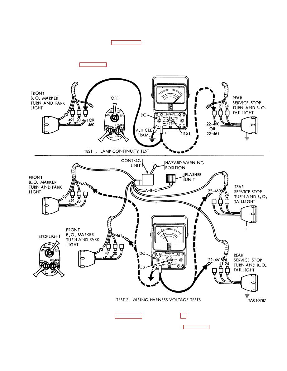
(2) Test 2. Perform the wiring harness voltage
black test lead to the vehicle frame. Touch the red
test. Set up the multimeter for dc voltage tests.
test lead to the center contact of the cable connector
D i s c o n n e c t connectors 460, 461, 22-460, or 22-
on the wiring harness. The voltmeter needle should
461, corresponding to defective light (fig. 2-40.1).
deflect at a rate of 1 to 2 times per second. If meter
Set the main light switch to the STOPLIGHT
needle does not deflect, leave the connector
position and the directional signal control lever to
disconnected from the light and perform the wiring
t h e HAZARD WARNING position. Connect the
harness continuity test.
multimeter as shown in fig. 2-40.1, test 2. Clip the
(1) Test 3. Perform
t h e w i r i n g harness
e. Directional Signal System Circuit (figure 2-
continuity test. Set up the multimeter for a con-
40.2) (Tests 3, 4 and 5 ) .
tinuity test (see fig. 2-8.4). Set the main light switch
Malfunction: Individual lamps do not light with directional
to OFF. Connect the black test lead to the vehicle
signal control lever in any position. Circuit: 460, 461, 22-460,
frame near the control unit. Remove the cable
and 22-461.

