TM 9-2320-366-20-4
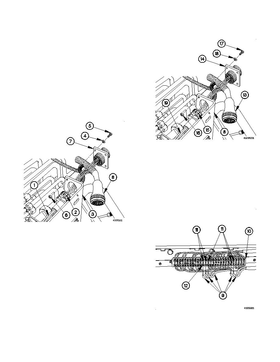
(5) Disconnect connector P107 (13) from connector J107
(14).
(6) Loosen back shell (15) on connector J107 (14).
(7) Remove four nuts (16), screws (17), washers (18),
control panel power cable assembly (19), and back shell
(15) from control panel (8).
b. Installation.
(1) Install control panel power cable assembly (1) and back
shell (2) in control panel (3) with four washers (4),
screws (5), and nuts (6).
(2) Install back shell (2) on connector J107 (7).
(3) Connect connector P107 (8) to connector J107 (7).
NOTE
Install plastic cable ties as required.
(4) Position five electrical wires (9) on terminal board
assembly (10) at positions 9,9,10,19,C (11).
(5) Tighten five screws (12) on terminal board assembly (10)
at positions 9,9,10,19,C (11).
7-551


