
TM 9-2320-272-24-4
5-3.
HEAD
(Contd)
REPAIR
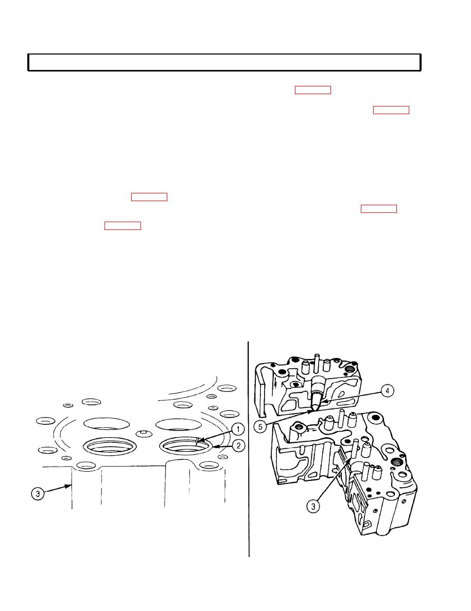
Check valve seat insert (2) and cylinder head (3) for looseness by tapping surface around valve seat
13.
insert (2). Replace valve seat inserts (2) that bounce when tapped (para. 5-4).
Measure width (6) of valve seat insert (2). If width exceeds 0.125 in. (3.18 mm) at any one point
14.
and cannot be narrowed during regrinding, mark valve seat inserts (2) for replacement (para. 5-4).
NOTE
The following examples of valve seat defects are provided to assist
in determining causes of failure.
Inspect valve seat insert (2) and cylinder (3) for cracks (1) and correct probable causes. If cracks
15.
exist, probable causes are improperly machined insert bore, improper fitting of insert in bore,
foreign particle under insert, faulty installation, and overheating.
Inspect valve seat insert (2) and cylinder head (3) for bums and correct probable causes. If burned,
16.
probable causes are carbon or foreign matter that prevents proper seating of valve. If burned,
resurface or replace (para. 5-4).
Inspect injector sleeves (4) and cylinder head (3) in accordance with instructions in para. 5-6. Check
17.
injector sleeves (4) for scratches with bright light. If scratched, mark injector sleeve (4) for
replacement (para. 5-6).
Check injector cup seating area (5).
18.
a. Lightly coat injector cup (11) with Prussian blue.
b. Install injector (9) into sleeve (4) with washer (10), clamp (8), and two screws (7). Tighten
alternately in 4 lb-ft (5.4 N.m) steps to 10-12 lb-ft (14-16 N-m).
c. Remove two screws (7), clamp (8), washer (10), and injector (9).
d. Check seat pattern in bottom of sleeve (4) and sleeve seating area (5).
e. Blued band (12) on sleeve (4) in sleeve seating area (5) must be 0.060 in. (1.52 mm) minimum
width and be located approximately 0.469 in. (11.91 mm) from bottom of cylinder head (3)
surface.
5-8
