
TM 9-2320-272-24-2
1.
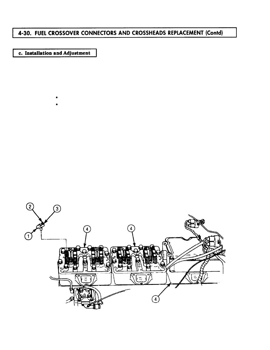
Loosen valve crosshead adjusting nuts (3) and back out adjusting screw (2) one full turn.
2.
Apply light film of clean engine oil to twelve valve crossheads (1) and install on guide (6) of cylinder
head (4). Ensure adjusting screw (2) faces toward manifold side of engine.
3.
Hold valve crosshead (1) down with finger pressure so it contacts valve stem (5) on side opposite
adjusting screw (2).
NOTE
It may be necessary to loosen locknut to complete step 4.
Ensure adjusting screw is lightly seated.
4.
Turn adjusting screw (2) down until it just touches valve stem (5).
5.
Set up dial indicator over center of valve crosshead (1) and zero-dial indicator while pressing down
on valve crosshead (1).
6.
Hold valve crosshead (1) down lightly and turn adjusting screw (2) in until dial indicator reads
0.025-0.040 in. (0.64-0.80 mm).
7.
Tighten locknuts (3) 22-26 lb-ft (30-35 Nm).
NOTE
If minimum clearance reading on dial indicator is not 0.025 in.
(0.64 mm), advance adjusting screw 1/3 of one hex on new valve
crossheads and guides or 1/2 hex on old crossheads and guides,
retighten locknut, and check clearance.
8.
Apply light coat of clean engine oil to eight new O-rings (8) and insert in fuel crossover connector
bores on cylinder heads (4).
9.
Install two crossover connectors (9) on cylinder heads (4) with eight new screw-assembled
lockwashers (7). Tighten screw-assembled lockwashers (7) 34-38 lb-in. (3.8-4.3 Nm).
4-212
