
TM 9-2320-272-24-1
THIS TASK COVERS:
b. Installation
a. Removal
INITIAL SETUP:
REFERENCES (TM)
APPLICABLE MODELS
TM 9-2320-272-10
All
TM 9-2320-272-24P
TOOLS
EQUIPMENT CONDITION
General mechanic's tool kit (Appendix E, Item 1)
Parking brake set (TM 9-2320-272-10).
MATERIALS/PARTS
Left splash shield removed (TM 9-2320-272-10).
Battery ground cables disconnected (para. 3-126).
Antiseize tape (Appendix D, Item 72)
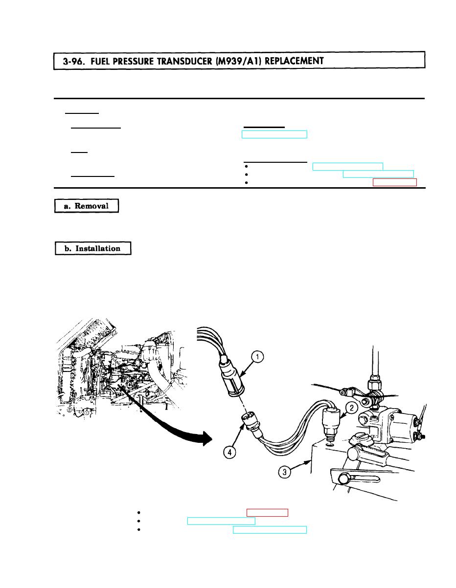
1.
Disconnect fuel pressure transducer connector (4) from harness wire (1).
2.
Remove fuel pressure transducer (2) from fuel pump (3).
NOTE
Male pipe threads must be wrapped with antiseize tape before
installation.
1.
Install fuel pressure transducer (2) on fuel pump (3).
2.
Connect fuel pressure transducer connector (4) to harness wire (1).
Connect battery ground cables (para. 3-126).
FOLLOW-ON TASKS:
Start engine (TM 9-2320-272-10) and check fuel pressure gauge for proper operation.
Install left splash shield (TM 9-2320-272-10).
3-271
