
TM 9-2320-272-24-1
Table 2-3. Electrical Troubleshooting (Contd).
MALFUNCTION
TEST OR INSPECTION
CORRECTIVE ACTION
13. ALTERNATOR OUTPUT VOLTAGE LOW
NOTE
If STE/ICE is available, perform NG50 - Charging Circuit Tests
Test 1. Check for loose, broken, or missing alternator or fan drivebelts.
a. Adjust loose drivebelts (M939/A1) (para. 3-78).
b. Replace broken or missing drivebelts (para. 3-78 or 3-71).
Test 2. Test battery voltage (malfunction 9).
END OF TESTING!
14. ALTERNATOR ADJUSTMENT
NOTE
Sealant must be removed from terminals before testing alternator
output.
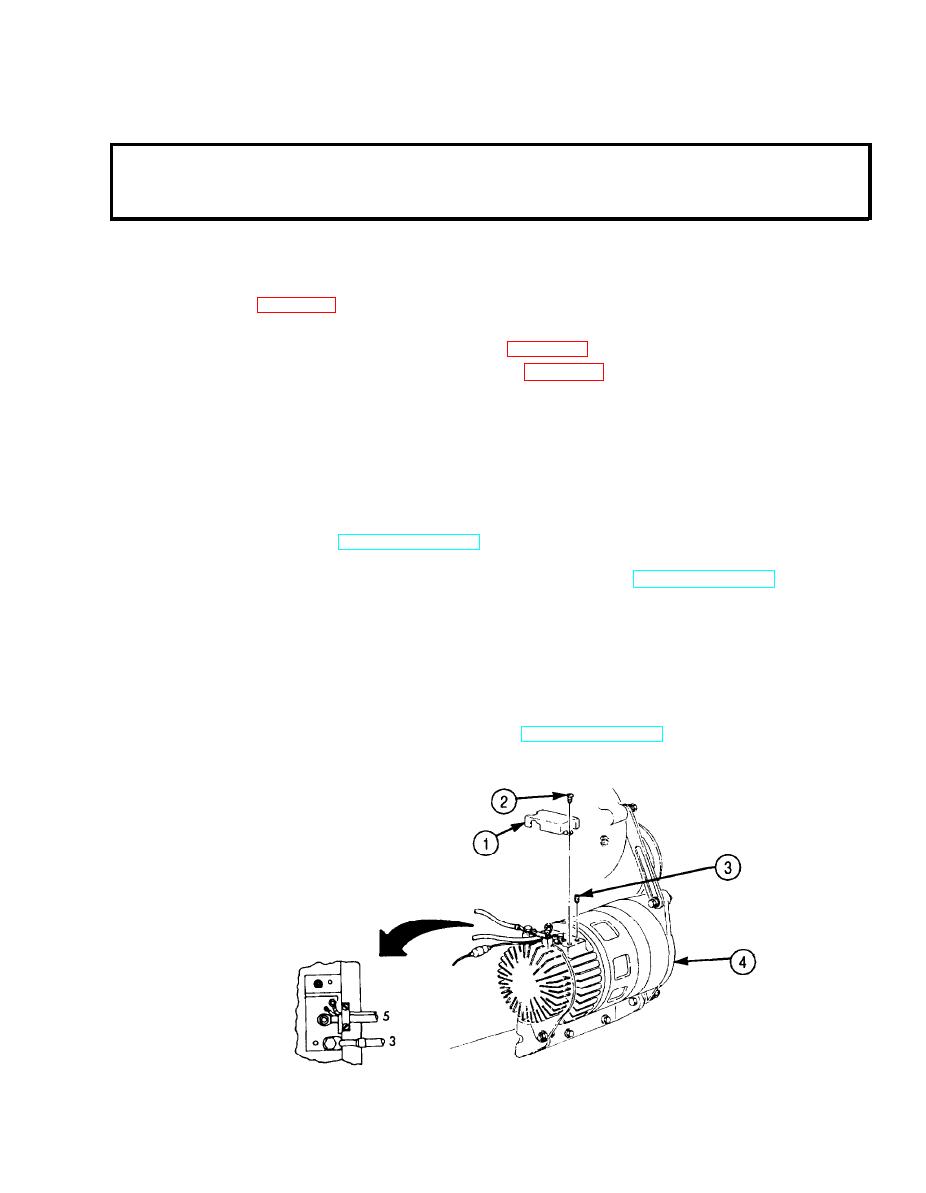
Step 1. Remove two screw-assembled lockwashers (2) and terminal cover (1) from alternator (4).
Step 2. Start engine (TM 9-2320-272-10) and raise engine speed above normal idle 600-650 rpm
(M939/A1), 565-635 rpm (M939A2).
Step 3. Put a load on alternator (4) by operating driving lights (TM 9-2320-272-10).
Step 4. Using multimeter, check alternator (4) output voltage. Connect black test lead to
ground 3. Connect red test lead to lead 5. Output voltage should be 26.5 to 29.5 volts. If
adjustment is required, go to step 5. If no adjustment is required, go to step 8.
Step 5. Remove pipe plug (3) from alternator (4).
Step 6. Turn adjusting screw counterclockwise to increase voltage; clockwise to decrease voltage.
Step 7. Apply sealing compound (Appendix C, Item 65) to threads of pipe plug (3). Using hex-
head driver, install pipe plug (3) on alternator (4) and tighten to 30-40 lb-in. (3-4 Nm).
Step 8. Turn off driving lights and stop engine (TM 9-2320-272-10).
Step 9. Seal terminal connections with adhesive sealant (Appendix C, Item 4).
Step 10. Install terminal cover (1) on alternator (4) with two screw-assembled lockwashers (2).
END OF TESTING!
2-123
