
TM 9-2320-260-20
2-20. STE/lCE DESCRIPTION AND OPERATION (Contd)
2. Numerical Readout. This type of readout is the measured value in units of the meas-
urement being made. If you are measuring 0-45 volts DC, the number 24 on display indicates 24 volts.
3. Error Readout. This type of readout indicates that wrong test number was selected
or transducer is not connected, or VTM is faulty.
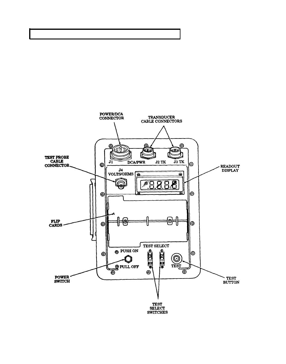
(e) Flip Cards. The flip cards list the 2-digit test number system for selecting various tests.
The cards also summarize test and operating instructions contained herein.
(f) Transducer Cable Connectors, J2 and J3. Connectors J2 and J3 connect VTM to two
W-4 cables and signals from transducers are supplied to VTM through the cables. Connectors J2 and J3
are identical and can be interchanged with each other or used in combination.
(g) Test Probe Cable Connector J4. Connector J4 connects W-2 cable to VTM when doing
manual voltage and resistance tests.
2-189
