
TM 9-2320-260-20
Table 2-4. Electrical Troubleshooting (Contd).
MALFUNCTION
TEST OR INSPECTION
CORRECTIVE ACTION
Test 2. Test wiring harness and circuit breakers (malfunction 27, test 7, steps 1 through 14).
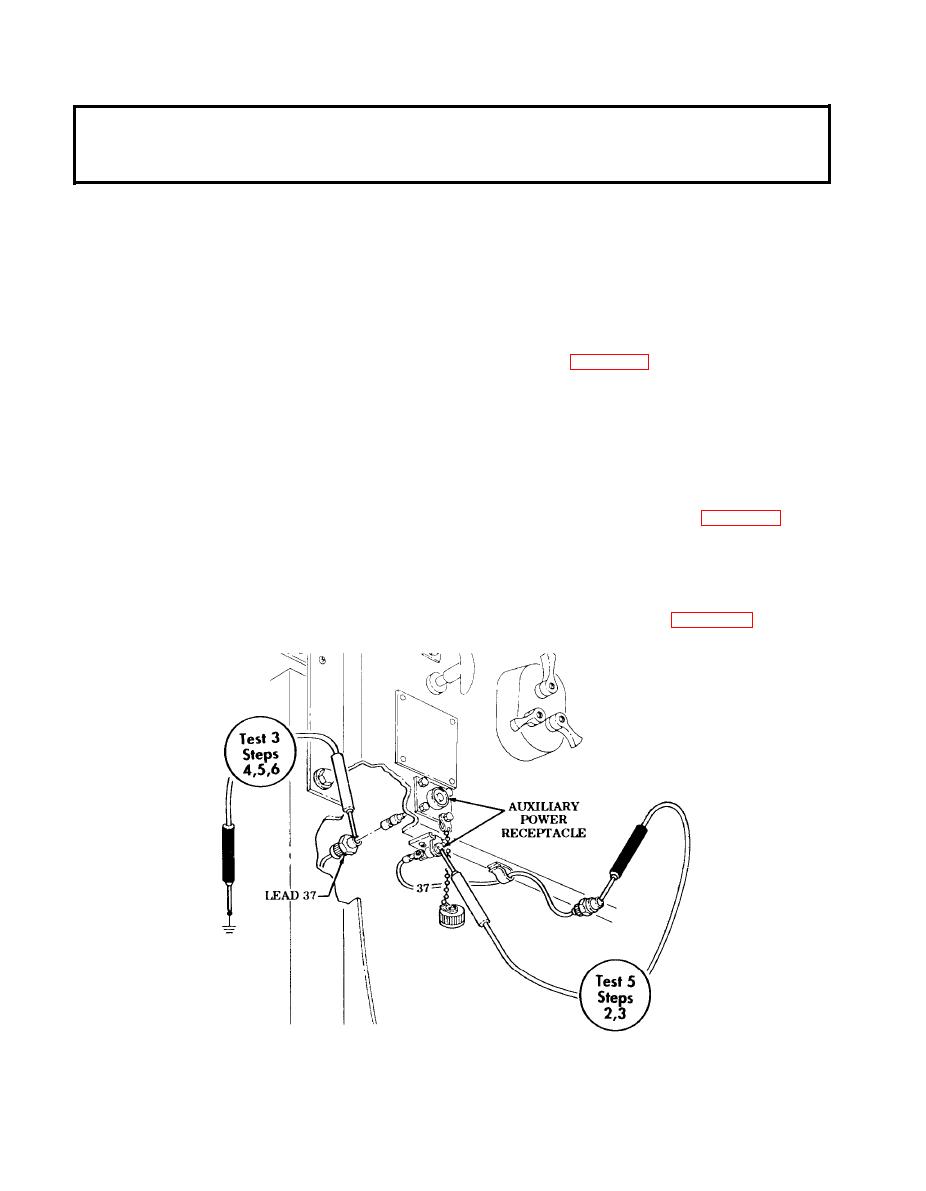
Test 3. Test connector for power output.
Step 1. Turn battery switch to ON position.
Step 2. Turn ignition switch to RUN position.
Step 3. Set multimeter to a range that will measure 24 volts.
Step 4. Disconnect lead 37 from connector.
Step 5. Touch positive lead of multimeter to contact end of connector.
Step 6. Touch negative lead of multimeter to frame ground. Voltage should be present.
a. If voltage is present, go to test 4.
b. Repair or replace lead 37 if voltage is not present (para. 4-52).
Test 4. Test auxiliary power receptacle for power output.
Step 1. Set multimeter to a range that will measure 24 volts.
Step 2. Install lead 37 into power receptacle.
Step 3. Turn battery switch to ON position.
Step 4. Turn ignition switch to RUN position.
Step 5. Touch positive lead of multimeter to contact end of power receptacle.
Step 6. Touch negative lead of multimeter to frame ground. Voltage should be present.
a. If voltage is present, go to test 5.
b. Repair or replace auxiliary power receptacle if voltage is not present (para. 4-22).
Test 5. Test auxiliary power socket for continuity.
Step 1. Set multimeter to RX1 scale.
Step 2. Touch positive lead of multimeter to contact end of power socket outlet.
Step 3. Touch negative lead of multimeter to contact end of opposite positive lead. Continuity
should be present.
Repair or replace auxiliary power socket if continuity is not present (para. 4-22).
END OF TESTING!
2-182
