
TM 9-2320-272-24-2
3-470. CTIS WIRING HARNESS REPLACEMENT (Contd)
b. Installation
CAUTION
Use care when routing CTIS wiring harness. Snagging may result,
and forceful pulling will cause damage to harness.
NOTE
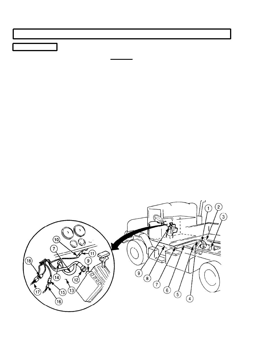
Perform step 1 if grommet was removed.
l
Route CTIS wiring harness and install tiedown straps as noted
l
in removal.
Install new grommet (14) on firewall (13).
1.
2.
Insert wiring harness (7) through grommet (14) on firewall (13), and pull wiring harness (7) into
engine compartment.
3.
Route wiring harness (7) along frame rail (8), crossmember (6), and frame rail (2).
4.
Connect wiring harness connector (1) to speed signal generator wire (23) on transfer case (5).
5.
Connect wiring harness connector (4) to pressure switch wire (24) located above wet tank (3) at
right frame rail (2).
6.
Position clamp (28) on wiring harness (7) and install clamp (28) on bracket (25) with washer (27)
and screw (26).
7.
Position clamp (31) on wiring harness (7) and install clamp (31) on firewall (13) with washer (29)
and screw (30).
8.
Connect wiring harness connector (22) to pneumatic controller solenoid receptacle (21).
9.
Connect wiring harness connector (19) to pressure transducer (20).
10.
Connect wiring harness connector (15) to blackout wire (16).
11.
Connect wiring harness connector (18) to power and ground cable (17).
12.
Connect wiring harness connector (10) to amber warning light wire (11).
13.
Connect wiring harness connector (12) to ECU receptacle (9).
A
3-1286

