
TM 9-2320-272-24-2
3-454. PNEUMATIC CONTROLLER AND RELIEF VALVE MAINTENANCE (Contd)
c. Cleaning and Inspection
For general cleaning instructions, refer to para. 2-14.
1.
For general inspection instructions, refer to para. 2-15.
2.
WARNING
Eyeshields must be worn when cleaning with compressed air.
Compressed air source will not exceed 30 psi (207 kPa). Failure to
do so may result in injury to personnel.
Dry all parts and clear all passages with compressed air.
3.
Inspect base plate (15), cover plate (3), and valve body (2) for cracks and stripped threads.
4.
Replace if damaged.
Inspect relief valve (27) for bends, cracks, and stripped threads. Replace relief valve (27) if bent,
5.
cracked, or threads are stripped.
Inspect wiring harness (6) for broken wires or cracked insulation. Replace wiring harness (6) if
6.
wires are broken or insulation is cracked.
NOTE
Perform step 7 if condition of wiring harness as inspected in step 6
is satisfactory.
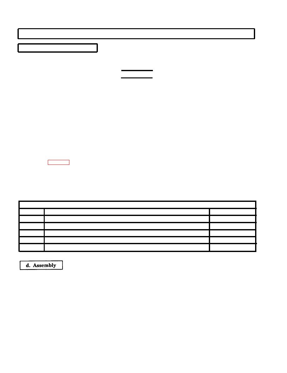
Using table 3-2, Electric Connections, check wiring harness (6) for continuity as follows:
7.
a. Check for continuity between pin A and pin E.
b. Check for continuity between pin A and pin F.
c. Check for continuity between pin B and pin D. Replace wiring harness (6) if continuity check a,
b, or c fails.
Table 3-2. Electrical Connections.
ELECTRICAL CONNECTIONS
LABEL
WIRE
PIN
____
Common
wire from inflate and deflate valve
A
_____
Common
wire from exhaust valve
B
Hot wire
from exhaust valve
C-CONTROL
D
D-DEFLATE
Hot wire
from exhaust valve
E
Hot wire
from exhaust valve
S-SUPPLY
F
Install three new O-rings (18) on valve body ports (19) and five new O-rings (20) on valve body
1.
ports (21).
2.
Apply a thin coat of petrolatum to two new valve cartridges (17) and new valve cartridge (16), and
install valve cartridges (16) and (17) on valve body (2).
3.
Install cover plate (3) on valve body (2) with four screws (4).
Install base plate (15) on valve body (2) with six screws (1).
4.
NOTE
Ensure marked wiring harness ends correspond to C, D, and S
marks on base plate.
5.
Install three new seats (13), new gaskets (12), and wiring harness (6) on cover plate studs (14) with
three nuts (7).
3-1238

