
TM 9-2320-272-24-1
1-22. ELECTRICAL SYSTEMS OPERATION (Contd)
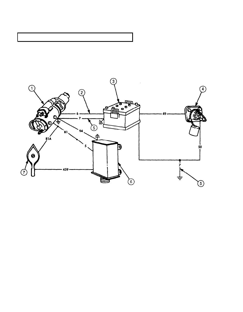
a. Battery System Operation.
The battery system is identical for all models covered in this manual and consists of the following
major components and circuits:
Key Item and Function
feed wire (circuit 81).
2 CIRCUIT 6 - Connects batteries to starting motor and to protective control box through circuit 81.
3 BATTERIES - Four 6TN batteries are connected in series parallel to provide 24-volts DC for
electrical starter system and 12-volts DC for the heater fan low speed.
4 SLAVE RECEPTACLE - Links an external power source directly to the slaved vehicle's batteries to
assist in cranking engine when batteries are not sufficiently charged.
5 CIRCUIT 7 - Provides a ground between starter, battery, and chassis.
6 PROTECTIVE CONTROL BOX - Protects the vehicle electrical system in the event battery system
polarity is reversed. Connects battery power to vehicle electrical lead through circuit 81 and circuit 5.
Connects positive ground through circuit 94 to the starter.
batteries to vehicle electrical load.
1-46

