
TM 9-2320-211-20
sheave and down through the boom, around the
rear sheaves (fig. 2-258).
(3) Insert the end of the cable in the hole in the
drum and tighten the hexagon-socket setscrew to
secure the cable to the drum.
(4) Wind the cable on the drum by moving the
hoist control lever to the UP position. Place a light
load on the cable while winding to insure a tight
and neat wind.
(5) Install the sheave guard (fig. 2-258).
2-311. Hoist Cable Sheaves and Guard
boom foot sheave is fixed on the pivot pin (fig. 2-
b. Boom Head Sheave and Upper Boom Foot
Sheave.
(1) R e m o v a l .
(a) Remove the four capscrews that attach
the sheave guard (fig. 2-258).
(b) Slack off the hoist cable, and remove the
cotter pin keeper from the upper sheave axle pin,
and remove the pin and sheave.
removed in the same manner.
(2) Installation.
(b) Position the upper sheave, and install
the axle pin. Secure the axle pin with a cotter pin
groove.
(c) S e c u r e t h e s h e a v e g u a r d w i t h f o u r
capscrews.
c. Lower Boom Foot Sheaves.
(1) R e m o v a l .
(a) Remove the sheave guard as in b (1) (a)
above. Slack off the cable tension.
(b) S e c u r e t h e b o o m a s s e m b l y w i t h a
suitable overhead hoisting device to hold it while
the pivot pin (fig. 2-258) is removed.
(c) Remove the pivot pin keeper nuts and
drive out the pivot pin to remove the lower boom
foot sheave.
(2) R e p a i r .
(a) Inspect the sheave guard for damage.
(b) If the sheave guard is twisted, dented, or
broken, straighten or weld it as required.
(3) lnstallation.
b. Installation.
(a) Position the lower boom foot sheave, and
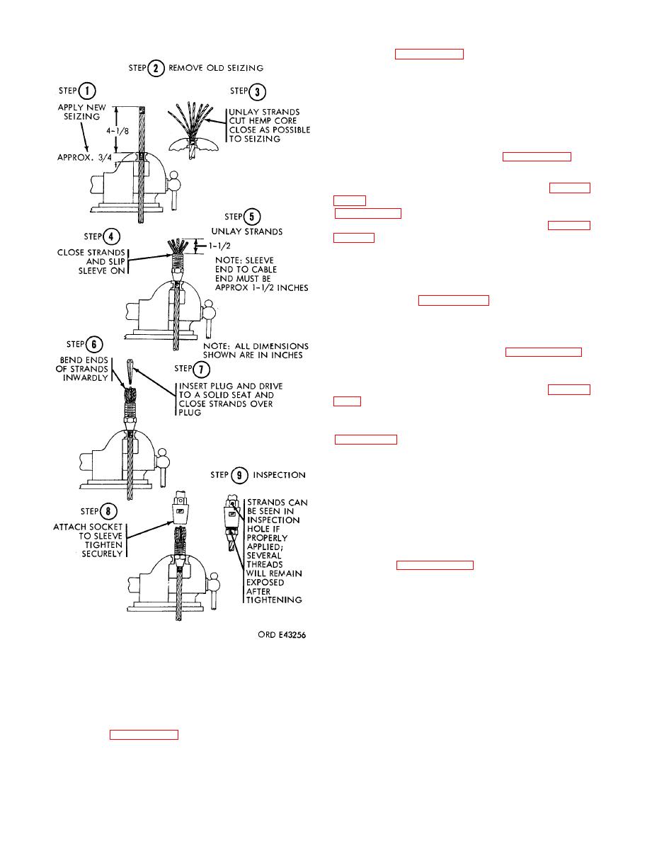
CAUTION
secure it with the pivot pin and nuts.
The
cable must be fully seated in the socket
(b) Remove the overhead hoisting device
and
visible through the inspection hole.
securing the boom assembly.
(2)
Install the hoist cable connector as in-
(c) Install the sheave guard as in b (2) (c)
dicated
above.
(2)
Thread the cable through the boom head

